Updates may be added. They will be appended below at the end. Watch for them.
--------------------------------------------------------
There were lots of official government X-planes and many related
craft, that led to the first generation
of supersonic-capable fighter aircraft (the “century series”, beginning with the F-100 Super Sabre). There were many “X-planes”, but only some of them were aimed at
this exploration of supersonic flight. Wikipedia
has a good list of all the official government X-planes. There were some other designations besides
“X-plane” that were also a part of this high-speed exploration. Those are included here.
I have compiled a table of those experimental craft which answered questions about transonic / supersonic / low-hypersonic flight of manned aircraft. That huge table is given in Figure 1. To see it (or any other figure) enlarged, click on any figure, and you can see all of them enlarged. There is an “X-out” feature at top right of that screen, which takes you right back to the article. That same enlargement procedure applies to any article on this site. See also Figures 19 and 20 below.

Figure 1 – Table of Data for Experimental Craft Intended to
Explore Supersonic Flight and Related Issues
There are two very important vehicles not included in the
table. These were never actually
built and flown: the Miles M.52 and the
X-20 Dyna-Soar. Wikipedia has good
articles on both of them. See Figures 2
and 3 for what these craft might have looked like.
The M.52 was a British effort to produce a manned aircraft
that could break Mach 1. That design had
straight wings, turbojet
propulsion, and a “flying tail”, meaning an all-moving horizontal stabilizer
instead of a fixed stabilizer with a hinged elevator attached to it. That “flying tail” technology fed directly
into the X-1 and the D-558-2 as retrofits,
and in everything since that flies supersonically. It was a crucial enabling factor! The M.52 did finally fly as a 30%-scale
rocket-powered model, breaking Mach 1 by
a considerable 30% margin, and only about
a year after the manned US X-1 broke Mach 1.
The X-20 Dyna-Soar was to be a suborbital-hypersonic / orbital
spaceplane for the USAF. The design
dates to the late 1950’s, and the
project was cancelled in the early 1960’s,
just as the first examples were coming off the Boeing manufacturing
line. It drew upon the results of the early
X-15 tests, and also the other earlier
X-planes and related craft, plus the
warhead re-entry work that went into the intercontinental ballistic missile
(ICBM) efforts. Seven astronauts were
secretly chosen in 1960 to fly it, among
them Neil Armstrong and Pete Knight,
both of whom later flew the X-15.

Figure 2 – The Miles M.52 That Was Never Built

Figure 3 – A Boeing Mockup of Its X-20 Dyna-Soar That Was
Cancelled
The nosetip and leading edges of the X-20 were monolithic
graphite with inserted zirconia rods to better conduct heat away from the
actual stagnation zones. The skins were
to cool by re-radiation of heat, but were
also insulated from the interior to reduce inward conduction. The pilot’s windscreen was covered by a heat
shield skin until entry was over, which
was then jettisoned so the pilot could see to land. It was to be launched by the then-planned Titan-3
ICBM. The work on the X-20 project fed
directly into the NASA Space Shuttle,
and its derivative the unmanned X-37B spaceplane now being flown by
USAF.
These high-speed flight projects began toward the end of WW2
(about 1944), based on questions, concepts,
and hardware items that became available from Germany, before and after that war’s end. These
included not only supersonic flight of manned aircraft, but also the use of swept wings as in the
Me-262 fighter, the merits of tail-less
aircraft as in the Me-163 rocket interceptor,
the merits of the delta wing as suggested by Alexander Lippisch, and the early concepts for spaceplanes, such as the 1941 Silbervogel (“Silver Bird”) proposal
in Nazi Germany for a trans-Atlantic spaceplane bomber.
Initial questions to be answered:
What
would it take to break Mach 1?
One very serious choice was “swept or straight wing?”, with most authorities at the time (end of the
war) believing that swept wings would be required to reach supersonic
speeds. The high-subsonic drag-rise
regime had already been successfully treated with swept wings by the Germans
during WW2, causing the Allies to try to
catch up on that technology after the war’s end. However,
some others sidestepped the unknowns associated with swept wings, and attempted supersonic designs with straight
wings (like the Miles M.52): notably
Bell with its X-1, and Douglas with its
D-558-1 Skystreak.
The all-moving-tail pitch control approach for
breaking Mach 1 came to the US from the British Miles M.52 project as a
possible solution to pitch control problems already encountered at high
subsonic speeds (approaching transonic) in a variety of aircraft, including some fatal power dives in the P-38
“Lightning” just before the US entry into WW2.
As soon as the “all-flying tail” approach was verified, it was incorporated as retrofits to the Bell
X-1 and the Douglas D-558-2 Skyrocket.
The all-moving tail has ever since been the standard for all supersonic
craft from the X-2 on, excepting those
with delta wings.
A final choice for breaking Mach 1 was “what
propulsion to use?” The choices
at the time were rocket, gas turbine, or mixed (parallel-burn) rocket-and-gas
turbine propulsion. The very early gas
turbines used in these craft were still rather weak in thrust performance, especially if not equipped with
afterburners. Only a little while later, turbine performance had very rapidly and
markedly improved.
The Miles M.52 and the Douglas D-558-1 Skystreak were
planned as gas turbine aircraft, while
the Bell X-1 was planned as a rocket-propelled aircraft. The Skystreak (flown from 1947 to 1953) did
break Mach 1, but only in a dive, and that was after the X-1 broke Mach 1
October 14, 1947, in level flight. The X-1 in its original form flew from 1946
to 1951. The Douglas D-558-2 Skyrocket
was designed as a mixed propulsion craft,
and was actually flown as gas turbine only, and as rocket only, as well as mixed rocket and gas turbine
propulsion, in the time frame from 1949
to 1956. It was a swept-wing
design.
The answers to these initial multiple questions directly supported
the “century-series” fighter designs,
notably the F-100 Super Sabre,
the F-101 Voodoo, the F-104
Starfighter, and the F-105
Thunderchief. See Figures 4-6 for images
of the X-1, the D-558-1 Skystreak, and the D-558-2 Skyrocket. There are good Wikipedia articles about all of
them. There is even a separate Wikipedia
article about the X-1 that lists all the flights it made. That last one covers
all three examples of the aircraft, the
date of the flight, its purpose, and the identity of the pilot.

Figure 4 – The Bell X-1 (straight-wing, rocket-powered)

Figure 5 – The Douglas D-558-1 Skystreak (straight-wing,
turbojet-powered)
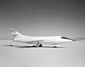
Figure 6 – The Douglas D-558-2 Skyrocket (swept-wing, mixed propulsion)
What
are the other effects of swept wings besides transonic drag reduction?
Adverse pitch-up and other instabilities at slow
speeds were soon identified while testing experimental aircraft with
swept wings. Understanding these
problems helped explain the “Sabre dance” behavior that resulted in several
crashes at landing speed with the F-100 Super Sabre. The possible solutions to low-speed pitch-up
and instability with swept wings were wing fences, leading edge slat devices, inverse taper, and variable sweep wings. All of these but inverse taper eventually
became “standard design practices” for swept wing designs, whether supersonic or not, although not all together.
The D-558-2 Skyrocket swept wing design was originally
intended to reduce transonic drag while reaching Mach 2, but it mostly got used to investigate pitch
stability issues and solutions between transonic and almost Mach 2, as well as supersonic underwing stores
carriage, during its flights between
1949 and 1956. It did break Mach 2 in a
very shallow dive, but never in level
flight.
The Bell X-2 was a swept wing design originally intended to
probe the high supersonic realm from Mach 2 to Mach 3, between 1954 and 1956. It and the revised X-1 designs identified
inertia coupling as a serious issue,
much aggravated by the thin air at high altitudes. The XF-91 investigated the inverse taper
distribution solution to low-speed pitchup problems, flying between 1949 and 1954. See Figures 7 and 8 for images of the X-2 and
the XF-91. There are good Wikipedia
articles about both of them.

Figure 7 – Bell X-2 Being Dropped From a B-50 (rocket-powered)

Figure 8 – Republic XF-91 with Inverse Taper Swept Wings
(mixed propulsion)
Of
what utility might a delta wing be?
The Convair XF-92 (flown from 1948 to 1954) was a gas
turbine-powered delta wing design. Being
a very first flying example, it proved
to have poor flying qualities,
and was not at all popular with the test pilots. But, it did uncover the surprising fact that thin-section
delta wings can provide extremely-high angle of attack capability at low
landing speeds! This unexpectedly very
high stalling angle-of-attack (near 45 degrees) was induced by strong
vortices on the suction side of the wing,
just downstream of the leading edge.
These are directly linked with the more usual wing root and tip
vortices. Non-delta wings (thin or not) do
not exhibit this behavior.
This work supported the Convair F-102 and Convair F-106
delta-wing “century-series” fighters, the
Convair B-58 “Hustler” bomber, the
Rockwell XB-70, and the Convair F2Y “Sea
Dart” for the US Navy, later
re-designated as the YF-7A. This work
has also since supported many of the modern tail-less aircraft designs.
Figure 9 depicts an XF-92.
There is a good Wikipedia article about it.

Figure 9 – The Convair XF-92 (delta-wing, turbojet-powered)
Are
tail-less designs useful at high speeds?
With simple flight controls, powered or not, the answer turned out to be “no”, as demonstrated by the Northrup X-4
“Bantam”, and the related history of the
US Navy with the Vought F7U “Cutlass”.
The X-4 flew from 1950 to 1953.
Figure 10 is an image of it.
There is a good Wikipedia article about it.
The related experiences of the Navy with the F7U are also
contained in a rather good Wikipedia article.
It was initially underpowered,
had unreliable hydraulics powering its flight controls, and exhibited too many difficulties (verging
on instabilities) landing on an aircraft carrier. That is why the Navy has since avoided most manned
tail-less designs except for delta-wings,
such as on the A-4 “Skyhawk”.
However, the
answer could be “yes”, but only with fully-computerized
flight controls, as
found later with fundamentally-unstable things like X-29, and related to many unmanned craft since.

Figure 10 – The Northrup X-4 “Bantam” (swept wings, tail-less,
turbojet-powered)
Questions that came up during testing:
Inertia
coupling in high-altitude thin air
This was a problem with X-1A-on (including the Chuck Yeager
flight to Mach 2.4 in the X-1A in 1953,
that barely avoided a crash), the
X-2 (leading to a fatal crash in 1956), the
NF-104 (leading to the famous ejection and helmet fire experienced by Chuck
Yeager in 1963), the X-15 (also leading
to a fatal crash in 1967), and it is
still a problem today with most big fighters at high wing loadings. See Figure 11 for an image of the Bell
X-1A, Figure 12 for the Lockheed NF-104, and Figure 13 for the North American
X-15. The Bell X-2 was already depicted
in Figure 7.

Figure 11 – Bell X-1A (X-1B,
X-1C, X-1D, and X-1E Were Very Similar)
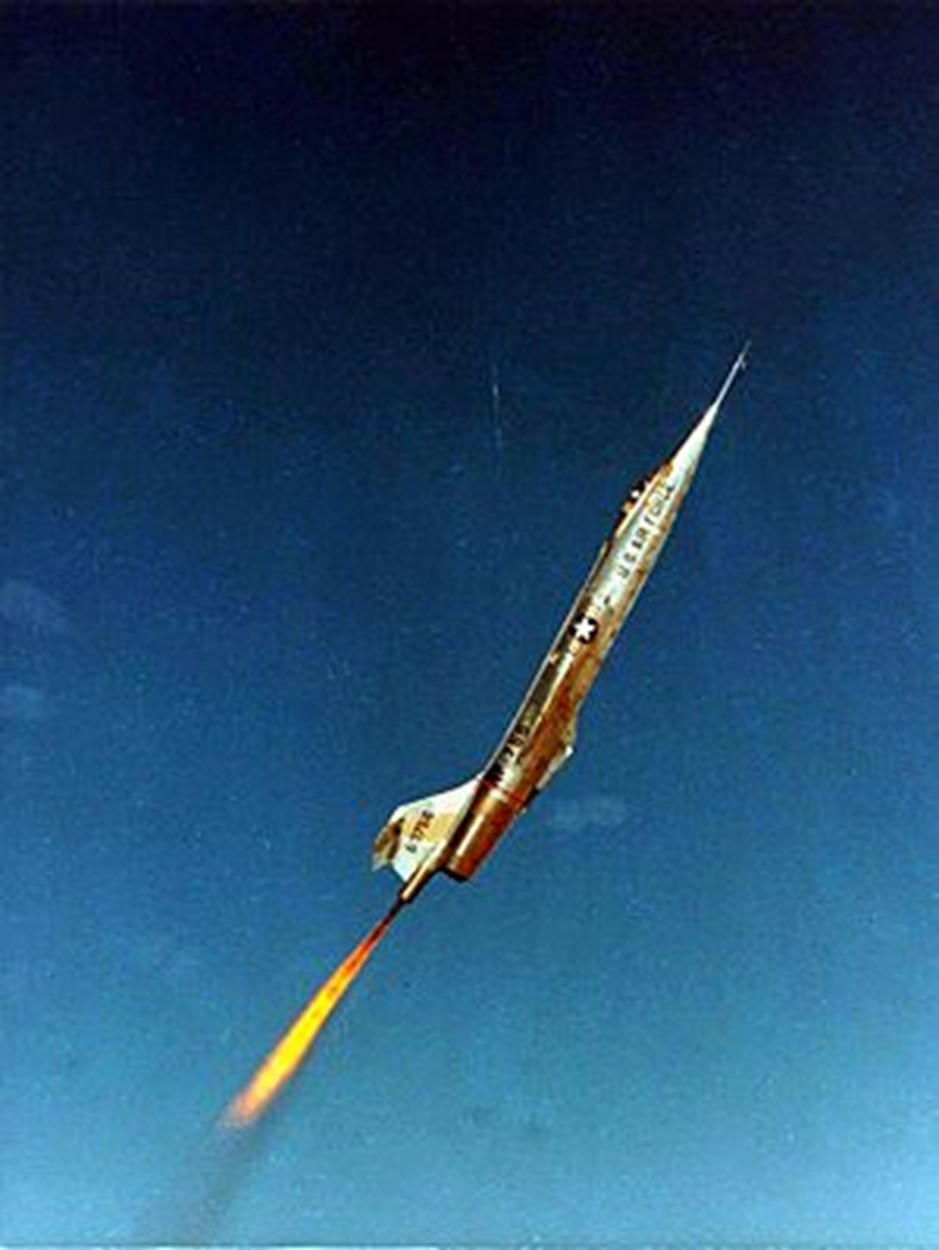
Figure 12 – The Lockheed NF-104, As Remanufactured From An F-104A

Figure 13 – The North American X-15, As Equipped With the “Big Engine”
While termed “inertia coupling”, this is fundamentally a situation where the
forces induced by the aerodynamic flight control surfaces are simply too small
for the corresponding inertias of the vehicle,
resulting in too-low (or zero) achievable recovery accelerations. This is more commonly experienced at extreme
altitudes in the very thin air, where
the control forces are inherently low due to low density, despite the high speeds. But at very high wing loadings (weight per
square foot of wing area), it can be
experienced even at low altitudes.
With the “Bell X-1A-on” series: the X-1A,
X-1B, X-1D, and X-1E actually flew. The X-1C was never built. All of these had a revised pilot cockpit with
a more conventional canopy, and an
ejection seat, unlike the original X-1. These models represent changes in wing
section and instrumentation. The X-1B
was the first of these craft equipped with attitude control thrusters, that were later included as part of the X-15
baseline design. Why? These experimental craft were reaching
altitudes above 100,000 feet (30 km), where
the air was simply too thin to permit normal control by means of aerodynamic
surfaces. The X-1E was a rebuild of the
X-1 #2 aircraft (“Glamorous Glennis”). The
rest were “built from scratch”.
The NF-104 was a modified Lockheed F-104A Starfighter to add
rocket propulsion and attitude control thrusters. It was intended as a trainer for astronauts
who were to fly space planes for USAF,
either sub-orbitally, or
orbitally, but it was not specifically built
as an experimental aircraft, in and of
itself.
By the time this craft flew,
gas turbine engines had advanced to point of enabling runway takeoff to
a rather high-altitude flight envelope “cap” near 50,000 feet (15 km). In a high path angle “zoom climb”, adding rocket thrust took the craft well beyond
the top of its normal flight envelope,
to near the edge of space, above (even
well above) 100,000 feet (30 km).
Attitude control thrusters were simply required up
there, for flight control, so that a nose-first “re-entry” into denser
air could be made, in turn allowing a
windmill re-start of the gas turbine engine,
which in turn restarted the aerodynamic flight control hydraulics. Any failure of this sequence could
well prove fatal! So, a de-spin chute mounted in the tail was
included in the design.
There was a JF-104 prototype for this craft, which had the attitude thrusters, but not the added rocket engine. It first flew in 1959, reaching around 80,000 feet. There were 3 mixed-propulsion NF-104 craft
delivered. 2 of these flew from 1963 to 1971. The number 3 craft was destroyed in the
famous Chuck Yeager crash in 1963. The other
2 reached altitudes of 100,000 to 130,000 feet multiple times.
Is
variable sweep really a feasible thing to do?
The answer turned out to be “yes”, as demonstrated by the Bell X-5, flown experimentally from 1951 to 1955, and as a “convenient chase plane” to 1958. The wings did not just pivot, the pivot point also translated
longitudinally, to keep the center of
lift near the same relation to the shifting center of gravity, as the sweep angle changed. This work supported the swing-wing designs
of the General Dynamics F-111, the
Grumman F-14, and the Rockwell B-1A and
B-1B bombers. There is a good Wikipedia
article about the X-5. A composite image
of it at various sweep angles is shown in Figure 14.

Figure 14 – Bell X-5 Variable-Sweep Craft (turbojet-powered)
How
do we stop adverse pitch-up & instability with swept wings?
The “band-aids” finally identified are flow fences and leading
edge slat devices. These were explored
with the D-558-2 (and inverse taper with the XF-91), which supported all the modern fighters after
the later “century series” (F-105), and
most modern jet airliners. Inverse taper
was, and still is today, not used; fences and slats are, whether the craft is supersonic or not. Leading edge offset (as on the F8U
“Crusader”) was found later, and is also
often used.
Variable wing sweep is the other basic approach, explored with the X-5. This work supported the F-111, F-14, and
the B-1A/B-1B swing-wing craft. It works
well, too, but is heavier.
What
happens above Mach 1?
This regime was thoroughly explored with the X-1A-on series 1953-1958,
the D-558-2 in the interval 1949-1956, and
was attempted with the Douglas X-3 “Stiletto” 1952-1956.
Of these, the X-3 was
far less than successful, mostly because
the turbine engines of the time were far too limited in performance. It exceeded Mach 1 in a steep dive, but never came close to Mach 2, much less the Mach 3 for which it was originally
intended.
The X-3 was a very “pointy” shape powered by two gas turbine
engines, and fitted with stub
wings. There is a good Wikipedia article
on it. An image of this craft is given
in Figure 15.
Work in this regime with the other planes supported the “century-series”
fighters, and later.

Figure 15 – The Douglas X-3 “Stiletto” (turbojet-powered)
What
happens above Mach 2?
This regime was explored by the X-1A-on 1953-1958, and the X-2 1952-1956. The X-3 was intended to explore this regime
up to Mach 3, but proved to be very unsuccessful
above Mach 1. This work supported the
later “century-series” fighters, and everything
faster since then.
What
happens above Mach 3?
This regime is quite extreme, and was explored with the X-2 1952-1956, and by the X-15 1959-1968 in 199 flights. Test pilot Mel Apt was killed in the X-2 in 1956,
after reaching Mach 3.2 at 65,500 feet. (At somewhat slower speeds, this same craft exceeded 120,000 feet.) The vehicle tumbled upon Apt attempting a coordinated
turn at those high-speed, thin-air conditions, due to inertia coupling. He attempted to escape, but that escape system design proved to be
utterly inadequate! The cockpit section
did indeed separate, but Apt was unable
to bail out of it before its impact.
I’ve seen the cockpit camera film of him being pinned and pounded, by too much cockpit section spin, to bail out.
His death in that crash ended the X-2 project, which at the time was the only way to reach
Mach 3.
The X-15 rolled out on 1958,
and first flew in 1959, with the “two
small engines” (XLR-11’s). There were 3
vehicles built. It first flew with the single
“big engine” (the XLR-99) in 1960. From
there it explored the regime from Mach 3 to Mach 6.7 at around 100-120,000
feet, and the really high altitudes of 50-60+
miles at somewhat slower speeds (nearer 2700 mph ~ Mach 4).
The number 3 vehicle was lost along with its pilot Michael
Adams on flight 191 in 1967, due to the
effects of inertia coupling (a “hypersonic spin” as the Wikipedia article terms
it). The aircraft finally broke up during
re-entry at about 60,000 feet,
scattering debris across 50 square miles. Adams was later posthumously awarded his
astronaut wings for exceeding 50 statute miles altitude on this flight.
The number 2 vehicle was rebuilt after an incident, with a little bit of extra length, a ceramic heat shield coating, and two external propellant drop tanks, as the X-15A-2. Pilot Pete Knight took this X-15A-2 version to
a record speed of about Mach 6.7 (4520 mph) at around 19.3 miles altitude (near
100,000 feet) in 1967, with a scramjet
test article affixed to the ventral fin stub.
See Ref. 3.
This record-setting max speed flight found shock-impingement
heating to be a very real danger,
with a scramjet test article as an adjacent nacelle on the ventral-fin
stub. This was because the shock wave off
the test article inlet spike very nearly cut the tail section off this craft, with high shock impingement-amplified heating
rates. As it turns out, the localized heating at the shock wave
impingement location was around factor 5+ times higher than what one would
otherwise expect at that Mach 6+ flight speed.
The 199 X-15 test flights supported the design of the Lockheed
SR-71/YF-12A, and also earlier the
Boeing X-20, and later-on the NASA Space
Shuttle. An image of the X-15A-2 is
shown in Figure 16. The envelope of
speeds and altitudes achieved during the X-15 program is given in Figure
17.

Figure 16 – The North American X-15A-2 With a Scramjet Test Article
On Its Ventral Fin Stub

Figure 17 – Speeds and Altitudes Achieved During the X-15
Program
How
can we train space plane pilots?
In the late 1950’s through the mid 1960’s this topic was a
real issue for the USAF. After all manned
spaceflight was taken from USAF, and
given to NASA, starting about 1965, this became much less of an issue. It remained only a bit of an issue with the
lifting body research vehicles through the end of the 1960’s into the
1970’s, for USAF. It took some time (to about 1969-1970) before
the last of the USAF manned space programs (the “Manned Orbiting Laboratory” or
MOL), was terminated. A lot of different reasons for this shift to
NASA were involved. That is not explored
here.
Training the space plane pilots took two forms: (1) simulating the low-speed landing
characteristics of low lift/drag vehicles,
and (2) flying the “typical” high-speed/high-altitude flight profiles
for sub-orbital / orbital ascents. The
item (1) issues were directly relevant to the NASA Space Shuttle vehicle and
the lifting bodies. The JF-104 and “factory-stock”
F-104’s were adequate to address this.
The item (2) profiles were based on the flight profiles for
the X-1, the D-558-2, and especially the X-15. Until the X-15, these involved flying to higher altitude at
high subsonic speed, diving to gain
supersonic speed, then pulling up into a
supersonic “zoom climb” at a high path angle above horizontal. From there,
rocket propulsion took one out of the sensible atmosphere. Upon re-entry, the idea was to restart the turbine engine, and fly back to a conventional landing. That is the design flight profile of the
NF-104. It was the zoom climb portion
into the extremely thin air that simulated space plane ascents.
It was actually the X-15 that ended that dive/pull-up/zoom
climb approximation. Its “big engine” XLR-99
propulsion was “good enough” to delete the dive to attain supersonic
speed. The X-15 simply accelerated the
vehicle to higher supersonic speeds at lower altitudes, or to lower supersonic speeds at higher
altitudes. X-15 or X-15A-2, it made no real difference, except in the exact numbers achieved. The “big” XLR-99 rocket engine in the X-15 really
was that good an engine/airframe combination!
Spaceplane pilot training in the USAF began with “stock”
F-104A aircraft, and the NASA-modified
JF-104 that had attitude thrusters. It
continued with the 3 delivered NF-104 craft that had mixed rocket / turbine propulsion
and attitude thrusters. These used the
Rocketdyne AR2-3 engine that burned jet fuel with high test hydrogen
peroxide. These flights supported the
X-20 Dyna-Soar that was cancelled, and
also the NASA Space Shuttle. The USAF
astronauts mostly went to NASA for the Space Shuttle program.
Rocket and Turbine Engines Used In These Planes
A variety of rocket and turbine engines were used in these
early experimental planes. Those data
are summarized in Figure 18. There are
good Wikipedia articles about all of these engines.
In particular, gas
turbine technology was in its infancy when these efforts started at war’s end. Pressure ratios and stage counts were
low, thrust-to-weight ratios were
low, and thrust-specific fuel
consumptions were high. The very
earliest engines did not have afterburners.
Performance factors improved at a very rapid pace. By the time the J-79 was installed in the
F-104 fighters from which the JF-104 and the NF-104 were derived, performance had approached what we might
consider relatively modern levels. This
showed up in vastly-improved aircraft performance.
The rocket engines were initially rather small and not
throttleable in the modern sense. The
initial designs used the same propellants as were used in the German V-2
ballistic missile (ethyl alcohol and liquid oxygen). The XLR-11 that powered the X-1 and some other
craft (including the initial X-15’s) addressed throttleability by being
4-chambered, with the ability to run any
or all of the chambers at their fixed thrust levels. That gave the XLR-11 a sort of “incremental
throttleability”, ranging from no thrust
to 6000 lb of thrust, in 1500 lb
increments.
Later, with the
XLR-25, XLR-99, and AR2-3 engines, continuous throttleability from 50 to 100%
became possible. In particular, the XLR-25 in the X-2 had two
independently-operating chambers of two different max thrust sizes (10,000 and
5000 lb), each throttleable from 50% to
100%. Essentially, by selecting which chamber was active, and what its throttle setting was, the engine could be managed anywhere from
2500 lb of thrust all the way up to the maximum sum of 15,000 lb of
thrust.

Figure 18 – Data About the Engines Used
Some Extra Details
The data table in Figure 1 is quite large. I have broken it into two figures here, for the avid reader. Figure 19 is a data table relating which
vehicles answered which questions, and
what the outcomes were. That is a sort of
testing logic “diagram”, if you
will.

Figure 19 – Which Craft Did What?
Figure 20 is a timeline diagram showing in which years each
of these planes flew. Be aware that the
end of the timeline scale is nonlinear.

Figure 20 – When Did They Do It?
On a personal note, I
was born in 1950, right in the middle of
the X-1, D-558-1, XF-91,
XF-92, and D-558-2 tests. I clearly remember Sputnik. I started aeronautical engineering school in
1968, just as the X-15 flights were
ending. My Dad was an aeronautical
engineer. I quite literally grew up
with this stuff.
How Might These Early Experiences Support Today’s
Interest In Hypersonics For Ascent to Orbit?
The key thing for that issue is the plot in Figure 17, showing the flight envelope conditions explored
with the X-15, relative to the feasible
paths for reaching orbit with aerodynamic ascent. That set of aerodynamic ascent paths is
actually quite narrow! 100 miles
is about 161 km, for those who prefer
metric. Similarly, 1000 mph is about 1610 km/hour (divide that
km/hour by 3600 to get km/sec).
Fly too low at too high a speed, and the aeroheating is simply too excessive
to endure, in any practical way. That is exactly what the figure says! Fly too high,
and the air is too thin to provide the lift for an aerodynamic ascent of
any kind. That is also what the
figure says! And, if you don’t have enough air to generate
lift, you also won’t have any
thrust, if you are trying to use
airbreathing propulsion in the form of a scramjet. See Ref. 1 for more information about that. If rocket,
the free-expansion nozzle designs are also limited by streamline
divergence effects at very high altitudes.
That is covered in Ref. 2.
One should note that vertically-launched rocket vehicles fly
well above this aerodynamic ascent path:
they leave the sensible atmosphere at relatively low speeds, and fly thrusted gravity-turn trajectories to
orbit, essentially in vacuum most of the
way. Such vehicles usually are moving only
around 1500 to 2000 mph, at altitudes
around 25-30 miles or so. That is actually
well to the left of the spaceflight conditions explored by the X-15
above the aerodynamic ascent corridor.
The X-15 achieved its maximum speed of about 4520 mph a bit
over 19 miles up (about Mach 6.7 at about 100,000 feet), which is right at the left end of the
“straight” portion of the aerodynamic ascent corridor. That is exactly where it identified shock
impingement heating as a very extreme risk,
thus severely constraining the vehicle configurations that might be
feasible for such an ascent (or re-entry).
The estimated effective temperature of the shocked plasma
sheath surrounding the vehicle at this flight condition is near 2000 K = 3150
F. That is the effective driving
temperature for the convective heat transfer to the vehicle, anywhere on its surfaces. Only the heat
transfer coefficient varies across these locations, by somewhere around a factor of 10+ between
stagnation zones and wake zones.
Parallel-mounted nacelles affixed to pylons or wings simply
cannot be made to work in this flight regime, as the localized heating where the nacelle shock
wave impinges on the wing or pylon leading edge is some factor 5+ higher than
one would otherwise expect at that speed and altitude, even for leading edge stagnation zones! Which in turn is why I don’t think the
proposed Skylon airframe, with its
wingtip-mounted engine nacelles, would
ever survive re-entry from orbit!
The inlet spike shocks impinging upon the adjacent wing leading edges, will simply cut the wings clean off! In a matter of seconds! That kind of rapid damage is what the X-15
found in that 4520 mph flight!
Again, see Ref. 3.
Some will point to the shape of the SR-71/YF-12A to deny
what I say about shock impingement heating risks. But they are wrong: that craft was NOT hypersonic! It typically flew Mach 3.2 at about 85,000
feet altitude. If it ever exceeded Mach
3.3, the pilots immediately took action
to slow back down, precisely to avoid
engine and airframe overheat damage!
I know, I have talked to a couple
of them.
Despite the shock impingement effects magnifying the heating
rates (not the temperatures!),
the SR-71 could withstand that heating,
because the driving temperature was only about 810 F = 700 K at that M3.3
overspeed limitation. Even beta-phase titanium
could withstand being fully soaked out to that temperature. But no more than that! The amplified heating rates just got it
fully soaked-out faster!
The far end of the “straight” portion of the corridor for
aerodynamic ascent is about 13,000 mph at about 25 miles altitude, according to Figure 17. Conditions there are quite a bit more
extreme. The effective temperature of
the shocked plasma sheath about the vehicle is some 5810 K = 10,000 F. Heat transfer coefficients are reduced a bit
relative to the left end, because the air
pressure is lower at that higher altitude.
This condition is actually probably at least fairly close to the max
heating rate point.
On this aerodynamic ascent corridor, the actual “entry” toward low orbit is just
about 17,000 mph at just about 70 miles.
The shocked plasma sheath effective temperature there is about 7600 K =
13,200 F. The density is so low that the
heat transfer coefficients are actually quite low. Therefore,
the peak heating rates are lower down,
earlier in the trajectory. No
surprise there! (Re-entry is similar.)
However, these
numbers do so very clearly indicate a very severe thermal problem to be
managed, if an aerodynamic ascent
to orbit is the goal. This is rather
like re-entry in reverse, except
the exposures are longer, especially
if your acceleration capability is limited!
And it will be very limited,
if you use only airbreathing propulsion for this task. Ref. 1 explains why, in terms of the “service ceiling” effect.
References
I wrote all of these.
They are all here on this “exrocketman” site. For finding references located on this
site, simply jot down the date and
title. There is a navigation tool on the
left side of the page. Click on the
year, then the month, then the title if need be. Ref. 4 has a much more comprehensive list of
articles, arranged by topic, concerning many different topics. Feel free to look at any or all of them.
#1. 1 June 2022, “About Hypersonic Vehicles” (covers both
rocket and airbreathing ascent)
#2. 12 November 2018, “How Propulsion Nozzles Work” (covers
conventional and free-expansion)
#3. 12 June 2017, “Shock
Impingement Heating Is Very Dangerous” (Mach 6.7 in X-15A-2)
#4. 21 October 2021, “Lists of Some Articles By Topic Area” (much
more comprehensive lists)
ADDENDUM (update 7-4-2022)
Here are some images of some of the aircraft these early experiments supported or confirmed. With one exception (the XB-70), these were not “experimental planes”, although perhaps a few of them should have been experimentals. There were serious difficulties with the F-102 Delta Dagger and the F7U Cutlass. The Dagger had to have its fuselage area-ruled and its intakes revised. The F7U was quickly replaced by the F8U Crusader.
First generation swept-wing supersonic fighters

North American F-86 “Sabre”
transonic fighter (Mach 1.02-capable), a
mainstay in Korea
Initial versions of the F-86 had leading edge slats. Those did not suffer from low-speed pitch-up and instability problems. Later versions deleted the leading-edge slats in favor of fixed leading edges for more fuel volume and range. Not surprisingly, those versions suffered from the infamous “Sabre dance” that afflicted the F-100 Super Sabre. Your only option is never to fly that slow at landing (at that high an angle of attack) with plain swept wings.

North American F-100A Super Sabre
(served through Vietnam)

McDonnell F-101 Voodoo (Mach 1.72-capable fighter bomber and recon)
Both of these aircraft (F-100 and F-101) lacked leading edge slats and suffered severely from low-speed pitch-up and instability problems. Yet both served successfully for long times. You just don’t fly slow at landing in plain swept-wing craft like these.

Lockheed F-104G Starfighter (this
one with Netherlands Air Force)
F-104’s were notoriously difficult and dangerous to fly, not because of swept wing problems, but because of inertia-coupling problems induced at high wing loadings by the stub wings, plus inherently high landing and takeoff speeds. The X-3 suffered the same troubles.

Republic F-105D Thunderchief with
Full Load of 750 LB Bombs in Vietnam
These still had low-speed pitch-up and instability problems, because they had plain swept wings. You just do not fly so slow at landing, and thus avoid the troubles.

Vought F8U “Crusader” – served as
top fighter 1957-1987
The “Crusader” introduced the offset wing leading edge as an alternative to wing fences. It worked. The other innovation was the variable-incidence wing, which reduced nose-high visibility problems during landing, extremely critical for landing on a carrier deck. This aircraft entered service armed only with four 20 mm cannons. Missiles were added later, after they became available. It served some 30 years as the Navy’s top combat air patrol fighter.

Grumman F11 Tiger (Mach 1.1-capable, replaced subsonic F9 Cougar)
These F-11’s had leading edge devices, as can be seen in the picture. These were good-handling aircraft, and were flown by the “Blue Angels”. These were capable of low supersonic speeds, replacing the swept-wing F9F-6 Cougar, which was high subsonic. The earlier F9 series were the subsonic straight-wing Panthers. All were carrier fighters and attack planes.
Early delta-wing aircraft
.jpg)
Convair F-102 Delta Dagger with
Area-Ruled Fuselage and Revised Intakes
This one entered service with severe drag and thrust problems. It took applying the “area rule” to solve the drag problem. Revising the air intakes fixed the thrust problem. Weapons were carried internally in a weapons bay. The usual weapon was the conventional-tipped air-to-air “Falcon”, but the nuclear-tipped “Genie” could also be carried. This aircraft was intended as an interceptor against incoming enemy bombers.

Convair F-106 Delta Dart
A bigger engine and better design from the outset made this one far more successful than its predecessor, the F-102. Both are the same basic idea, however: a delta-wing supersonic interceptor with internal weapons storage. Again, the weapons were the “Falcon” and the “Genie”. The advantage of this design approach is at landing, where very high angle of attack capability reduces touchdown speed. There is a nose-high visibility problem, aggravated by the high angle of attack at touchdown.
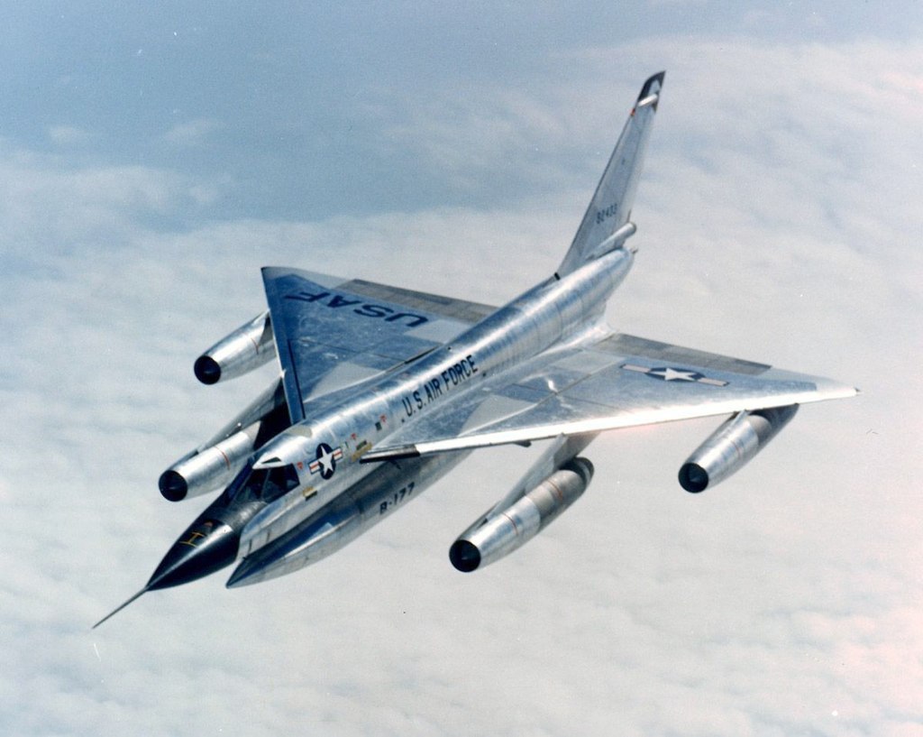
Convair B-58 “Hustler” Supersonic Bomber
(served, but soon replaced by older Boeing
B-52 as strategic bomber)
This one entered service as a supersonic-capable bomber (for penetrating Soviet air defenses) that otherwise cruised at very high subsonic speeds. It could not maintain supersonic flight on 3 engines, though. Loss of an engine would cause a fatal problem with center of gravity vs center of lift, as the aircraft suddenly decelerated subsonic. It would turn broadside and break up.
This was due to an extreme shift in the center of pressure between what obtained subsonically, and what obtained supersonically. Once supersonic, fuel was pumped aft for a more rearward center of gravity. If it then suddenly went subsonic, the aircraft was unstable, pitched up broadside, and broke up faster than its crew could react.
Despite initial pilot resistance, the solution was an automatic fuel pumping system to adjust center of gravity forward again, immediately upon detecting an engine problem. The real issue to resolve was that this had to be done much faster than humans could react. It had to be automatic.
The B-58 entered service after the
B-52, but eventually was replaced by the
older B-52 as the preferred strategic bomber.
This is because the higher speeds and lower internal volume of the B-58
incur more drag and more fuel consumption with less fuel capacity, rendering the B-58 capable of only a 1-way
flight from the US to Russia.
Orbiting at the fail-safe point,
awaiting the “go code”, was
simply not an option with the B-58.
But it was, with the B-52. Which loiter capability is really what made
the B-52 the preferred strategic bomber.

Rockwell XB-70 Valkyrie (Mach 3 bomber
experimental prototype – 2 built, 1
crashed)
This design (XB-70) was intended for an even more-invulnerable high-supersonic penetration of Russian air defenses, similar to the B-58, but much faster. It suffered the same basic mission problems as the B-58: (1) it was a one-way trip, and (2) there was no orbiting at a fail-safe point awaiting a “go code”. Development was terminated in favor of Mach 3 experimental work, accordingly. The Russian Mig-25 was intended to be the interceptor to counter it. That interceptor was the fastest gas turbine-powered aircraft ever flown, at Mach 3.5 max, but with an inherently short engine life.
.jpg)
Convair F2Y Sea Dart (dual-ski version), more-or-less an experiment
This one probably should have been an “experimental”. The need for waterborne ski takeoffs “evaporated” in favor of catapult launch from aircraft carriers with angled flight decks.

Douglas A-4 “Skyhawk” (delta wing
but also with horizontal tail)
This one combines the high angle of attack capability of the delta wing with the positive pitch control of actually having a horizontal tail. It was a very, very successful design. One nickname was “Heineman’s Hot Rod”. My Dad working at Vought knew Ed Heineman at Douglas.
I have seen one of these A-4’s making multiple low high-speed passes at the Mojave airport. It was doing just about 0.9 Mach, at just about 3 or 4 feet above the runway. The aircraft would have had to climb, in order to lower its landing gear. Very impressive!
Tailless designs

Vought F7U “Cutlass” (carrier fighter, not so successful, replaced by Vought F8U “Crusader”)
Landing on aircraft carrier flight decks in all conditions proved to be a problem with tail-less aircraft designs, if fitted with simple flight controls, powered or not. The deserved nickname for this one (the F7U) was “widowmaker”. The Navy has since for several decades avoided tail-less designs for its manned carrier aircraft. Tail-less was a sort of “design fad” in the mid to late 1950’s, based on the notion of parasite drag reduction. It proved to be less than desirable, ultimately. Much more effective pitch control with a horizontal tail proved to be far more important.

Vought Regulus 1 Missile
(successful but superseded by SLBM)

Vought Regulus 2 Missile (from USS
Grayback, superseded by SLBM)
Not having to land on an aircraft carrier flight deck, the two tail-less Regulus missile designs were actually rather successful despite the pitch control deficits incurred by the tail-less designs. They were simply superseded by the submarine-launched ballistic missile (SLBM), initially Polaris. Regulus 1 made operational missile patrols on US Navy submarines. The faster Regulus 2 was to replace it, but the submarine-launched cruise missile concept was superseded by SLBM’s before Regulus 2 could be fielded.

Northrup SM-62 Snark Missile
(superseded by SAC ICBM)
The tail-less Snark strategic cruise missile had several real control problems, including pitch control, leading to the expression “Snark-infested waters” at the site where it was tested. Fortunately, it was also superseded by the intercontinental ballistic missiles (ICBM’s) of the Strategic Air Command (SAC).
Swing-wing designs
Unlike the other aircraft pictured here, these were not first generation anything. The swing-wing concept was not used in first generation designs. Its use came later, starting with the B-1 bombers.

North American Rockwell B-1A
Prototype (4 Built)
The four B-1A prototypes proved-out the basic concept. Some changes were made to enhance low observability for the B-1B production model. Avionics systems integration in the B-1B was done by USAF instead of Rockwell. That did not turn out so well: there are 3 systems critical to successful penetration of very dense air defenses. Only 2 of these systems can be “on” simultaneously, because of severe interference problems that “crash” all of them. Fixing this required all-new avionics, which were about 2/3 of the aircraft price, so that was never done. Accordingly, the B-1B cannot be, and is not, used for penetrating very dense air defenses.

North American Rockwell B-1B “Lancer”
(100 Built and Most Still Serving)

General Dynamics F-111 “Aardvark” Fighter-Bomber,
mostly used as a bomber, now retired

Grumman F-14D “Tomcat”, long-serving but now retired
The F-14 is famous enough to need no comment here. Its replacement is the fixed-wing FA-18, which fills not only the fighter role, but also the attack bomber role.
Swing-wing designs work, they are just heavier than fixed-wing designs. If you have enough thrust, you can fly pretty-much fly anything that is heavy, albeit with due regard to inertia coupling. Swing-wings do allow much slower landing speeds for a craft that can fly high supersonic with highly-swept wings. You just won’t like the range and payload penalties induced by the weight and volume of the swing-wing mechanism. And you might not like the enhanced risk of low-altitude inertia coupling, if you let the wing loading get too high.
ADDENDUM 2 – Airplanes I Have Flown (update 7-5-2022)
I flew several aircraft long before I ever attempted a pilot’s license. My Dad and Mom both obtained private pilots’ licenses from FAA when I was a young boy. Dad had been a B-25 pilot for the US Army Air Corps at the end of World War 2.
Both Dad and I were aeronautical engineers. He had his BS and his A&P. I earned a BS and an MS before going into the workforce. (My PhD came much later in life, in general engineering, not specifically aeronautical engineering.) My greatest pride came when Dad started asking me my opinions about aeronautical things, based on what he perceived that I knew.
When I was very young, Dad obtained the wrecked airframe of a 1940 Piper J-5 Cub Cruiser. He rebuilt that aircraft and put it into the air. It had no electrical system, no lights, no radio, and required hand-propping to start. It was restricted to day VFR flight, accordingly. He and Mom got their private pilot licenses in that aircraft when I was about 9 or 10 years old.
I was about 13 years old when Dad first taught me how to stick-and-rudder fly, in that airplane. At that age, I wasn’t very good at it, but I did make many takeoffs and landings in it, plus some cross-country trips with Dad. Figure B-1 is an image of such an airplane. The J-5 is a 3-seat Piper Cub, with a real door. The one pictured is not my Dad’s old airplane, just one similar.

Figure B-1 – Image of a Piper J-5 Cub Cruiser
The next aircraft that I flew came about as the product of a
Boy Scout deal with the transport pilots at what was then the Dallas Naval Air
Station. I was about 16 years old when I
did this. My Scout unit (Explorer
Post, actually) took a dead-reckoning
navigation course from these Navy transport pilots, at the end of which we got to go with them on
their monthly proficiency flight.
Back then, the
transports at “Navy Dallas” included two Korean War-vintage C-118/DC-6/R6D
aircraft, and one World War 2-vintage
C-54/DC-4/R5D aircraft. The transport
pilots did not want to fly the older World War 2 bird unless the other two were
“broken”, because of significant old-age
maintenance issues with the older craft.
As luck would have it,
only the old World War 2 bird was flying the night we Scouts went with
them on their proficiency ride. So, we flew around Dallas and Ft. Worth instead of
to Oklahoma City and back. Same total
flight time, just at the indicated stall
speed of 170 KIAS. That’s all it would
do.
My turn in the copilot’s seat came as we were near Ft.
Worth. Under the direction of the Navy
pilot, I held the aircraft in steady
flight, then in a coordinated turn about
what was then Carswell Air Force Base,
and then again in level flight. I
did not make any landings or takeoffs in this airplane. But I did very well flying it, as directed by the Navy pilot. Figure B-2 is an image of such an
airplane.

Figure B-2 – Image of a C-54/DC-4/R5D Aircraft
I did fly a small aircraft once, while a college student, at about age 20. This was a Cessna 150. I did not make any landings or takeoffs in
it, but I did take it through a split-S
turn at about 2-3 gees, when told to
make a turn and not to be timid about it.
Figure B-3 is an image of a Cessna 150 aircraft.

Figure B-3 -- Image
of a Cessna 150
My Dad sold his Piper J-5 and acquired a 1952 Cessna 170B in
the 1960’s. This was another wrecked
airframe that he rebuilt. He had it
flying by the 1980’s. I bucked rivets
for him as a junior high schooler, as he
slowly rebuilt it. I went on several
cross-country trips with him in it, plus
some landings and takeoffs. I was almost
40 years old by then. This was all
stick-and-rudder flying, paper
charts, pencils, and nothing but a VOR. See Figure B-4. The one pictured is not my Dad’s plane, just something similar.

Figure B-4 – Image of Cessna 170B
While working at Baylor University in the Aviation Sciences
department, I had the opportunity to fly
in a Beech King Air with the department chair.
This was my first flight in the cockpit of a turbine aircraft, at around age 50. I did a couple of takeoffs and landings
flying about the pattern. The handling
was much heavier than Dad’s Cessna, of
course. See Figure B-5.

Figure B-5 – Image of a Beech King Air
Once my Dad became too ill to fly anymore, I took possession of his Cessna 170B, and started flight training in it, in my mid 60’s. I wanted to take Dad up for one more ride
before he passed away, but that was not
to be. See Figure B-6 for an image of my
Dad’s Cessna 170B housed in my hangar at the McGregor, Texas,
airport. I built the
wood-and-angle-iron tailwheel guideway over the gravel. I called it “Interstate double-aught-and-7/8”.
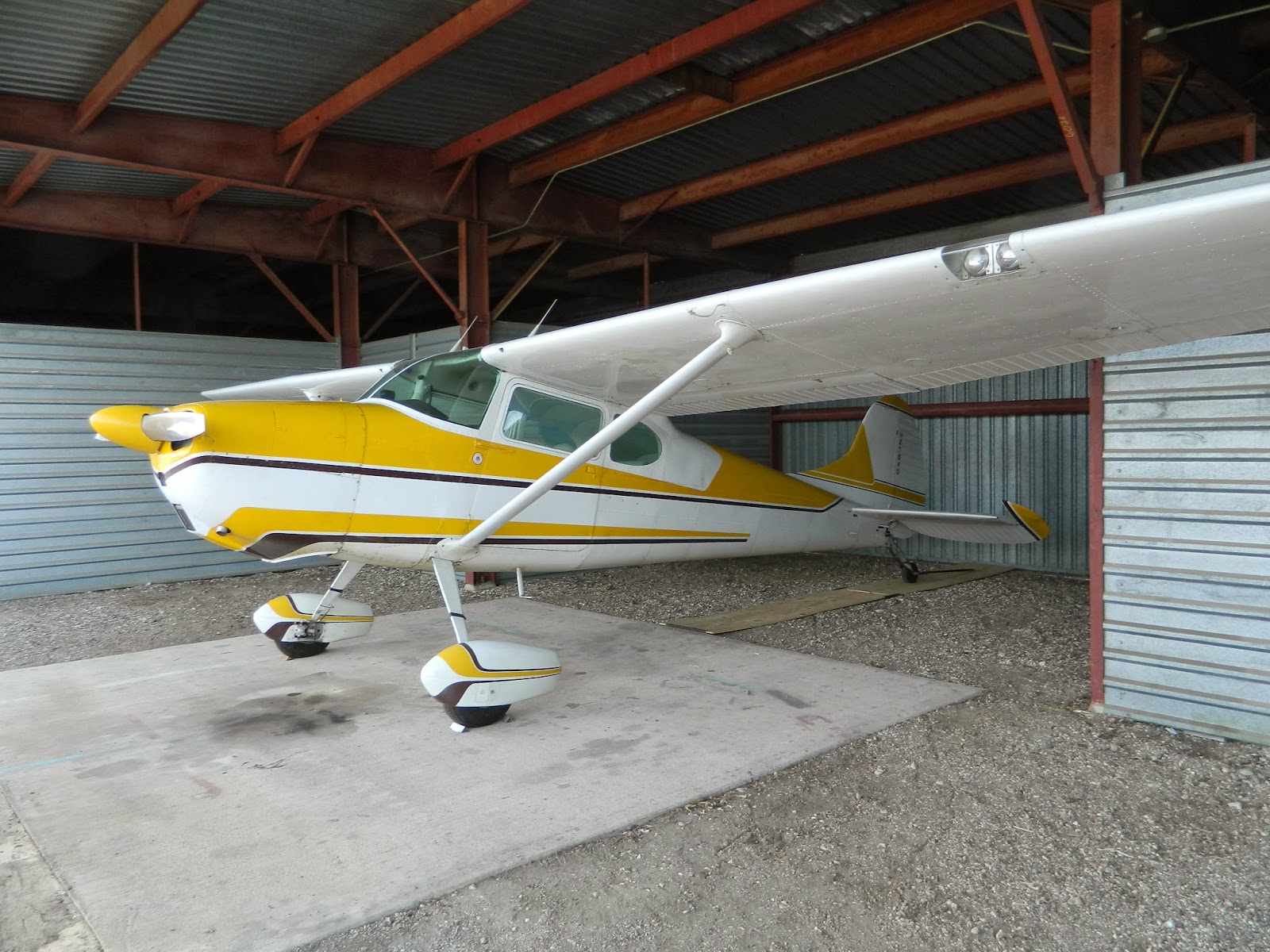
Figure B-6 – Image of Dad’s Cessna 170B In My Hangar
Then after Dad passed,
I had a mild stroke. I grounded
myself, lest this should ever happen
again, with me alone at the
controls. That ended my flying.

No comments:
Post a Comment