This is not the text or the presentation form of my paper to be presented August 6 at the Mars Society convention in Dallas. But, it is a shortened version of the major points. I did include all of the figures here, which pretty much speak for themselves.
The title of the paper is
GOING TO MARS (or anywhere else nearby), for which the document date is July 17, 2011. It is a refinement of pencil-and-paper bounding/feasibility work I did in fall and winter 2010, sitting in the recliner with just a calculator and a spreadsheet, in the evenings.
SUMMARY OF RESULTS:
The study was aimed at going to Mars, but the same vehicles could be used anywhere in the inner solar system inside the orbit of Mars: Mars, Venus, Mercury, and the near Earth objects (NEO’s) which include some asteroids.
I made entirely-different assumptions about what was important and what were appropriate constraints on the mission and vehicle designs:
This is a clean-sheet design. The differences with other studies are: (1) legacy hardware and contractors are absolutely not required, (2) new developments are minimal, (3) maximum self-rescue is designed into every phase, and (4) all known requirements and risks for life support absolutely take precedence over any other factors in the design.
I got startlingly different results for what is possible and how hard and expensive it might be, results far different than anything I’ve seen published in decades:
One 9-month round trip, 6 men, 16 one-week landings, nothing thrown away, minimal technology developments (but fairly certain of success), no new launch rockets, under $8 billion in direct launch costs, possibly as soon as 5 years.
A wild guess for the overall program might be 3-4 times that amount (around $50 billion in 2010 dollars), if done by a team of lean, efficient, well-focused contractors, with a lean, efficient, well-focused government agency leading it. Compare that to Apollo 4 decades ago: 6 brief landings of 7 attempted, for around $200 billion in 2010 dollars. (We know more now.)
A further startling result:
All mission assets are reusable, and left in place around Earth and Mars for the next missions to refuel and reuse.
The assumptions made for this study really are quite different from those of any other Mars mission study this author has ever seen, or heard about. It should therefore be no surprise that the results obtained here are at considerable variance with the expectations of most folks knowledgeable of this field of endeavor.
That difference does not invalidate these results!
STARTING POINT:
I started with a proper definition of the
true mission objective. That brings up the question of what is exploration, what do we want from it, and where does it fit within the larger scheme of things? I used the best model from 500 years ago for the voyages to the New World from Europe, and its subsequent exploitation and settlement. See figure 1, which points out that an exploration mission must answer
two crucial but deceptively simple questions. Experimental and economic bases and colonies come later, as the figure shows. Note the differing roles of government and industry in those different phases.
They are very important!

Figure 1 – The Most Successful Model in History for Exploration and Colonization
Carrying this out means these landings are
not just Apollo-style “flag-and-footprints” missions with “a towsack full of surface rocks” as the “science return”. It also means we make many landings in one trip, to make the effort worthwhile.
That is quite a different mission objective. I have not seen that idea proposed since the 1959 Disney movie about going to Mars.
MISSION ARCHITECTURE:
Apollo did identify two different ways to reduce required launch rocket size, but only used one of them. See figure 2. Since both are effective, and we currently have no gigantic launch rockets, why not use both architecture options in a single mission design? That’s what I did in this study: see figure 3.

Figure 2 – Choices of Mission Architecture for Apollo to the Moon

Figure 3 – Use Both LEO Assembly and LMO Landers to Reduce Launcher Size
IMPACT OF LIFE SUPPORT ISSUES:
Figure 4 lists the known life support issues, and indicates their characteristics and time dependence effects. One should note that we do not yet know how to do a closed-cycle ecology. That would be a major technology development, especially since once we can do it here, we have to adapt it for spaceflight.
Another thing to consider is that we do not yet know how to preserve packed food acceptably beyond about a year and a half; that is another major technology development.
A third thing to consider is that we have no direct experience with the potential therapeutic effects of fractional gee for the artificial gravity issue. Surrogate studies (bed rest) simply cannot be trusted enough to risk lives.
Surrogates are not exact models!
The only real, trustable experience we have is at 1 gee and zero gee. But, artificial gravity solutions at 1 gee and 4 rpm will be big (56 m radius), heavy, difficult to build, difficult or impossible to maneuver while spinning, and horribly expensive.
(See the 7-31-11 posting for more details on this issue.)
The net message is that everything in figure 4, combined with what we know and can do today, points toward
planning zero-gee manned missions with flight times under one year. Since minimum energy mission plans call for 2-3 years round trip,
we will have to find a way to fly the men very much faster: we need some “hot rod propulsion”.

Figure 4 – Life Support Issues Are Time-Dependent
EFFECT OF AVAILABLE LAUNCHERS:
Some typical launchers are shown in Figure 5. Most of these are flying. There are a couple no longer available, and a couple not yet flying, shown in the figure. SpaceX’s Falcon family has by far the best cost per unit payload to LEO in the industry. Its Falcon-9-heavy should make its first flight next year, meaning it should be available in a timely fashion for this design.
I was using 2010 data right off SpaceX’s website for this, to set my dockable module size at 32 metric tons maximum. In February 2011, they revised their payload figure to 53 metric tons, which just makes things better. However
I did not go back and redo my study for that change. The figure shows that update in red. The price range for 2011 also updated, but is still centered near the 2010 value, so I did not update that in the figure.
Oops, there's a typo in fig 5: the payload for Falcon-1 is 1.01 metric tons, not the value shown. I used 1.01 tons in my analyses, no errors there.

Figure 5 – Selected Launcher Data
LANDER AS A CRITICAL DESIGN ITEM:
The total weight of landers and landing equipment thrown to Mars is a critical issue for vehicle size, the number of launched modules to create those vehicles, the total number of launch rockets required, and thus total effort and expense.
Landing coverage on Mars requires that we consider plane changes in the lander “burns” for descent and ascent. I used 30 degrees (arbitrary), so that from an ecliptic-derived 25 degree inclined parking orbit, I could cover plus or minus 55 degrees of latitude. With a little plane change capability in the transfer vehicle to achieve a higher parking orbit inclination of 60 degrees, polar coverage is possible.
The landers will be too large to benefit much from aerobraking on descent, but will need a bit of heat protection. Min mass thrown to Mars requires these landers to be reusable to the greatest extent possible. Rocket braking descent and rocket ascent with 30 degrees plane change sets the two way velocity change requirement at 12 km/s. This is out of reach of chemical propulsion single stage with a rugged inert weight fraction of 20% and a decent payload fraction of 10%.
Figure 6 shows the best choice to be a solid core nuclear thermal rocket (NTR) for a single stage reusable lander. This is a technology extensively tested 4 decades ago that came within a year or two of flying, as the NERVA engine. It is not a major technology development, although it needs to be recreated along with the supporting expertise (engineering art).

Figure 6 – Why a Nuclear Rocket Single Stage Reusable Lander Makes Good Sense
How we use that lander ties directly into the objective of exploration (answer the two questions “what all is there?” and “where exactly is it?”) and also the selected mission architecture. Crew safety also gets into this as top priority.
We send that lander down with an armored inflatable Quonset hut along the lines of the Bigelow Aerospace space station modules, to be erected at a safe distance from the radioactive reactor core of the lander engine. We use a crane for loading access, which is part of the unusual equipment to be made part of this lander’s inert structural weight, along with some sort of refueling probe and the landing legs.
The crew comprise a pilot/engineer, a geologist/geochemist, and a biologist/biochemist. They are cross-trained well enough to assist, or even fill in for, one another. We send lab equipment they can use to do most of the science on-site, during their nominal week-long stay on the surface at each site.
We send a rover car big enough to use as an equipment transporter as well as an exploration vehicle. It has a real drill rig on it, capable enough to sample at least a km down. We also send small robot mini-rovers with this crew to assist in exploring and sampling.
We split the Mars mission “vehicle” into a fast manned vehicle capable of returning just as fast on its own fuel if rendezvous at Mars fails, and a number of “slowboat” unmanned vehicles that bring the landers (with equipment) and all of the landing propellant supply. The one-way “slowboat” velocity-change requirement, with some plane-change capability, is about 8 km/s.
Since the lander engine is solid core NTR, and 8 km/s is well within its single-stage capability at reasonable inert mass fractions, we also use the nuclear landers as the unmanned transfer propulsion. This avoids the introduction of a third propulsion item for those vehicles.

Figure 7 – Baseline Site Camp Scenario with the Single Stage Nuclear Lander
This lander needs landing legs and a squat form factor for stability on potentially rough ground. A cartoon of it with all the data and characteristics is given in figure 8, and its estimated performance in figure 9, relative to min (no plane change) and max (30 degree plane change) velocity-change requirements.
CREW SAFETY ISSUES REGARDING LANDER USE AND NUMBER:
Crew safety concerns demand that 3 persons stay in orbit (doing science from there), while monitoring 3 persons on the surface. We must have one lander “in reserve”, ready to use as a rescue vehicle, whenever a lander is on the surface. We must have 3 landers, so that if one becomes inoperative, we need not terminate the entire mission. The rescue crew is 1 man.
3 landers sets the number of “slowboat” unmanned vehicles, each with 1/3 of the landing propellant supply, that must be assembled from 32 ton modules by docking in Earth orbit. This is much like the modular assembly of the International Space Station (ISS).
I would have liked multi-engine landers, but the nuclear engine design does not scale or throttle well enough to do that. It will just have to be tested more and proven fully reliable.

Figure 8 – Configuration Layout and Data for the Reusable Single-Stage Lander

Figure 9 – Estimated Performance and Requirements for Lander
IMPACT OF LIFE SUPPORT ISSUES DRIVES TRANSFER HABITAT DESIGN:
The living space requires something around half the available volume per person of the old Skylab space station of the 1970’s. This station was “super roomy” for 3 men up to half a year. It weighed about 85 tons. A design of 3 32-ton modules docked together matches the weight of Skylab pretty closely, although this form factor is a bit skinnier.
Safety demands that all 6 crew be able to shelter for a day or two from solar flare event radiation. (The slow drizzle of cosmic rays is mitigated to acceptable levels simply by round trip travel times under one year.) Solar flare radiation can be shielded by water or wastewater, and maybe a little steel plate placed strategically.
Safety also demands that
critical mission flight maneuvers be conducted, solar flare event or not. Therefore the
vehicle flight deck is the radiation shelter, and it needs to be surrounded by the habitat water and wastewater tanks. One transfer habitat module is rigged for these functions, as shown in figure 10. The second module must be wide open to provide the open living space, and a place for eating, exercise, and recreational activities. The third is a combination crew dorm and packed storage module, which also provides the privacy function.

Figure 10 – Three-Module Crew Habitat Section Layout
CREW RETURN DRIVEN BY SAFETY AND EXISTING TECHNOLOGY:
I “reversed-engineered” the data on SpaceX’s website to estimate performance of its Dragon capsule, and how much more velocity-change I could get with extra thruster propellant tanks in the unpressurized section, see figure 11. It may need a bit thicker heat shield, as the emergency “bail-out” free return velocity is over 16 km/s. This craft looks like an excellent crew return vehicle as well as emergency return. One modified Dragon could carry all 6 crew; I used 2 for the safety of redundancy.

Figure 11 – Modified Spacex Dragon Capsules as Crew / Emergency Return Vehicles
MANNED VEHICLE “PAYLOAD”:
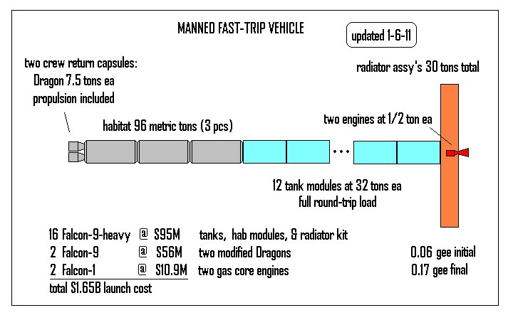
The figure 10 crew transfer habitat plus the two figure 11 modified Dragon return vehicles are the payload of the manned vehicle to be assembled (and recovered) in Earth orbit, all “single stage” in the sense of jettisoning nothing. The remainder of this vehicle is its propellant and its “hot rod propulsion”.
A LOW-RISK PATH TO “HOT ROD PROPULSION”:
I picked a nominal 75 days to cover a nominal 100 million km, essentially straight-line, flight path, to and from Mars, on both sides of a single opposition. These add up, with 16 weeks at Mars, to a nominal 9 month mission. That’s under the year limit for life support without artificial gravity, with a time margin in case something untoward forces us to slow down a little.
Figured as a simple square-wave velocity-distance trace, the average coast cruise is almost 16 km/s. The departure and arrival velocity changes are roughly equal this magnitude at each end of the trip. For safety’s sake, we must carry the propellant for the return trip in this vehicle, just in case rendezvous should fail at Mars. That’s double the one-way requirement.
So, the total velocity requirement is then about 62 km/s, way beyond the capability of solid-core NTR single-stage at believable inert weight fractions. We have to have “thrusty” propulsion, around 6000 s of minimum specific impulse, to meet this requirement, because we also need around 0.05 gee vehicle acceleration to make these burns effectively “impulsive”.
This “hot rod propulsion” is the only development item. To minimize the development risk, we must pick “not from scratch” items, and we need two worked in parallel, to ensure one will be ready when we need it. It would help if they both use a cryogenic liquefied gas as propellant, so that we could use a common propellant tank module for all vehicles, as in figure 12.

Figure 12 – Rough-Out Layout of the Common Propellant Module
There are two good candidates meeting all those requirements: the hydrogen-propellant open-cycle gas-core NTR of 4 decades ago (see figure 13 for the estimated characteristics), and the argon-propellant VASIMR engine being developed by former astronaut Franklin Chang-Diaz in Houston. Both would be multi-engine designs technically, as well as for safety. I personally know more about the gas core NTR, so I show it in the illustrations.
(See "changes" in the 8-9-11 post above.)

Figure 13 – The Open-Cycle Gas Core Nuclear Thermal Rocket
The gas-core NTR was never tested propulsively 4 decades ago, but did come within about 2-3 years of it, so
it is not “from scratch”. Controllable gas phase fission, and the necessary fireball containment flow pattern were successfully bench tested back then. Putting them together and testing a series of engine designs is the technology development path here.
VASIMR is being tested at the 200 KW power level, and may soon flight test on the ISS, so it
is not a “from-scratch” development. Its strong point is high efficiency. Its weakest point is the electrical power source. The tradeoff between scale-up and number of thrusters is as yet undetermined for this mission. It will need a space-worthy, flight-weight nuclear-electric power plant, likely in the multi-MW range. We already know how to build those down here. The technology development item is making those power plants space-worthy and flight-weight.
HOW ALL THIS FITS INTO A PLAN AND VEHICLE DESIGNS:
There are four vehicles to assemble in LEO from docked modules of a maximum 32 metric tons. Three are unmanned “slowboats” that bring the landers and all the propellant for the landings to Mars on one-way trips. The other is the fast-trip manned vehicle with the “hot rod propulsion” that is recovered intact and complete in LEO after the mission is done.
All assets are left in place in orbit around Mars and Earth for future missions to refuel and re-use, which is of tremendous technical and economic benefit. See figure 14 for the final mission plan. Figures 15-18 describe the vehicles.

Figure 14 – The Basic Mission Plan

Figure 15 – Unmanned Vehicle Configuration for the Mars Mission

Figure 16 – Estimated Performance and Requirements, Unmanned Vehicle

Figure 17 – Manned Vehicle Configuration for the Mars Mission

Figure 18 – Estimated Performance and Requirements, Manned Vehicle
FINAL COMMENTS:
There is another technology needed to carry this out: a dexterous, rugged, lightweight space suit. This is presumed to exist by the time these vehicles are being assembled in LEO. That suit will be needed for lander refueling operations, and for use on the surface of Mars. I would suggest a mechanical counterpressure design, but I also strongly suggest that the required compression level requirement be honestly investigated, not simply presumed equal to the traditional 1/3 atmosphere of the gas balloon suits we have been using. See the article on this same blog site titled
Fundamental Design Criteria for Alternative Space Suit Approaches and dated 21 January 2011 for more details about that.
This is not an optimized design, it is just a ballpark exploration of what is feasible under these very realistic assumptions and constraints. The crew size, number of landings made at once, details of rendezvous in LMO, and a host of other details, all need exploration and optimization with far more rigorous calculations than this.
However, all of these other possibilities will be found to operate within the same basic ballpark that this study identified: that is, multiple vehicles to Mars, manned items flying very fast, combined use of LEO and LMO rendezvous to reduce launcher size to something reasonable, and multiple landings from a single mission.
The real critical factor for success is not any of the technical things,
but in having lean, efficient private and public entities to do this work.
The same basic vehicles and components can be used to visit anything in the inner solar system within the orbit of Mars; i.e., anywhere the round trip manned vehicle flight time is under 1 year. One simply adjusts the number of common propellant tank models in each stack to meet or exceed velocity change requirements.
For Mercury, the same four vehicles are used. For Venus and the NEO’s, men cannot land, so only the manned vehicle need be used. The moon is too close to require this kind of vehicle, although it could travel there.
The Good News
This particular study design adds up to a direct launch cost for Mars of about $8 billion (2010 dollars), based on cost figures right off the SpaceX website, and the total number of launches to orbit all of the required modules. A set of “lean” contractors led by a “lean” government agency could actually get this done rather quickly, in perhaps as little as 5 years. In this context, “lean” means
dedicated, focused, efficient organizations, unhampered by outside bureaucratic or political interference.
Done by “the usual crowd”, the cost would be many, many times higher, and the timeline at least 15-20 years, if it could be done at all. We’ve seen this before. Ever since Apollo, really.
The Bad News
The NASA that could lead and manage this project as presented herein, is very most definitely
not the NASA that we have.
We have an enormous government space agency trying to do an entire plethora of things, in which every little project is a budgetary line item and “political football” in Congress. This is a Congress that now arrogantly “designs” heavy lift rockets (that we may or may not even need) by pork barrel politics instead of engineering realities!
It is this author’s opinion that we have not done the government space agency function correctly for some 40 years now, which in large part explains why men have not flown anywhere new in all that time. (I have little hope we can really change that.)
But, that’s another topic.