Update 3-13-2026: As indicated in this article, multiple friends and launch enthusiasts then touted, and still keep touting, aerospike nozzles for SSTO, based on the false supposition that good atmospheric performance will prove to be good in vacuum. It WILL NOT! It cannot. Compressible flow physics says so! And most of the dV to LEO will be expended out in essentially-vacuum at low performance, between around 45 and 150 km altitudes.
I have since come up with better, more defendable, ways to estimate the average cosine component factor that is the effective nozzle kinetic energy efficiency. I will be posting another aerospike article on this site in early April 2026, with those better numbers. It shows the same kind of performance fall-off as shown in this article, only the numbers are slightly different.
This is due to free surface plume spreading while the flow is still attached to the spike, as you fly into vacuum. In vacuum that spreading is extreme. Down in, and below, the stratosphere, it is not.
The "promise" of good aerospike nozzle performance as you fly out into vacuum has been selling a lot of technology development programs over the many years. None has yet flown into space. When one does, it will prove to be a "disappointing surprise". But that should be no surprise at all!
The plume spreading effect has been seen on every single launch rocket as it flies into vacuum, since the space age began. It does not degrade conventional bell performance, because it takes place AFTER the stream has left the exit! Up to that point, all the streamlines are still confined to nearly-axial directions by the walls of the bell. That confinement does NOT happen with the aerospike, by its very design! The same is true of any other free-expansion "altitude compensating" design! It is inherent!
The aerospike (or any of the other free expansion designs) has its proper application in the first stage of a TSTO, not an SSTO! Most, to almost all, the first stage burn is made down in the sensible atmosphere, where the nozzle efficiency of the aerospike is high. Low nozzle efficiency cuts both thrust and specific impulse!
-----
original article:
-----
I have corresponded with multiple friends recently over the merits of using an aerospike engine versus a conventional bell nozzle engine for flying from Earth’s surface into low Earth orbit. I conducted a design analysis using such nozzles, without pushing the state-of-the-art right to the edge, and I found even the sea level conventional bell to be much superior in vacuum.
What I uncovered during my design sizing analyses was: (1) not only was unconfined streamline
divergence a very serious problem for aerospike designs, as I have maintained for some years now, but also (2) there is a strong effect
favoring lower chamber pressures! Unless
one sharply reduces design chamber pressures,
the streamline divergence problem degenerates into complete infeasibility
at very low altitudes indeed. That
chamber pressure reduction has a big negative effect upon the thrust and
specific impulse that one can achieve,
including the effects of somewhat lower chamber c* velocity.
I did in fact confirm that my “roughly 60,000 foot
altitude” point, beyond which aerospike performance
falls while conventional bell performance does not, is
indeed correct! While still a
rather fuzzy boundary, my analyses do
show poor aerospike performance not far above that critical altitude.
Here Is Where I Started
I had done some nozzle evaluations and published an earlier
article on this topic (ref.
1). The free-expansion designs I
evaluated for that article were a twin-spike single-throat approach, not an annular or linear aerospike, but the behavior and physics are quite
similar. That is the genesis of Figs. 1 and 2.

Figure 1 – Basic Flow Physics of Conventional Bell Nozzles

Figure 2 – Basic Flow Physics of Aerospike Nozzles and Other
Free-Expansion Designs
The fundamental lessons as I initially understood them
are:
#2.
Free-expansion designs, including the
aerospikes, have ever-increasing
streamline divergence as ambient atmospheric pressure drops, while the expansion Mach number
increases. This leads to an
ever-increasing potential momentum term (and there is no pressure term) in
thrust. However, the streamline divergence angles quickly lead
to low cosine-components of the streamtube momentum vectors in the axial thrust
direction. At higher altitudes, this divergence inefficiency effect completely
overwhelms the larger momentum effect,
with the result that performance actually falls with altitude.
This Is What I Did
For the conventional bell cases, I used “typical” chamber c* = 5900 ft/sec for
LOX-RP-1 at 1000 psia Pc, from ref. 2, a modest modern max Pc = 3000 psia, a modest pressure turndown ratio (TDR) of
3, and a massflow bleed fraction of 5%
to drive the turbopumps. I did not
change the c* for the min Pc value, as
it is a small effect over that small a Pc range. The other variables were much more important.
I used the sea level chamber and throat design as the basic
common gas generator, by forcing the
design thrust levels for two higher-altitude designs (60,000 feet and 30,000
feet) to produce the same throat area At and flow rate values as the sea level
design. That produces a very fair
comparison, conceptually just
substituting one bell design for another onto the same chamber, throat,
and pump assembly, while also operating
at the same chamber pressures and propellant flow rates.
I used a simple empirical equation to estimate separation
pressure ratios from the bell’s average half angle. It works very well for conical nozzles, and runs slightly conservative with curved
bells:
Psep/Pc = (1.5 * Pe/Pc)0.8333
For the aerospike nozzle,
I started with that same Pc = 3000 psia gas generator, and sized low in the stratosphere, but the streamline divergence effects were
infeasibly extreme at 28 x 2 degrees.
The numbers simply made little sense.
I did notice a definite improvement at the min Pc over max Pc!
Therefore, I revised
the gas generator design to a max Pc = 300 psia, c* = 5700 ft/sec (reflecting the drastically-lowered
pressure range), TDR = 3 as before, and the same 5% bleed fraction. I sized for 100,000 lb thrust at 10,000
feet, using an aerospike that started at
56 degrees to axial, to zero the fan
angle at design. That gave me numbers
that actually made sense, and looked
very realistic.
I selected that design point thrust so that the sea level
thrust was comparable to the sea level bell design at 100,000 lb. That gave me flow rates somewhat higher than
the fixed-bell designs, primarily
because of the lower c* associated with the order-of-magnitude-lower range of
chamber pressures.
I used the Prandtl-Myer flow model of supersonic expansion
around a corner to estimate the flow divergence angles at the edge of the plume, based on the expected expansion Mach number
as determined by the Pc/Pa ratio. The
equations for Prandtl-Meyer expansion come from Ref. 3.
The orientation of the gas generator throat axis is the same
as the slope of the aerospike at its forward end, so that the attaching stream starts out
parallel to the adjacent surface. If it
were to impinge more directly, that
would induce a strong shock wave train on the aerospike surface, as it turns toward the axis direction, with corresponding large pressure
losses, disrupting the expansion.
I finally picked a 56 deg x 2 deg shape for the
aerospike, with the ring of thrusters 56
deg off axis at its start. The
Prandtl-Meyer angle gets that 56 deg subtracted off, because of thruster orientation, to determine the actual lateral divergence
fan angle of the plume relative to the thrust axis. Below design altitude, you get negative fan angle data, because the plume geometrically contracts due
to the changing shape of the aerospike. The
end of the aerospike is a small angle whose cosine is always near 1. Nozzle kinetic energy efficiency is just the
average of the cosines of the inner and outer angles.
At design, I used straight
axial and the aft aerospike angle to calculate the effective nozzle kinetic
energy efficiency. Both below and above design
altitudes where the plume edge is off axial,
I used the average of the fan angle cosine and the 2 deg aerospike
cosine, for my effective nozzle kinetic
energy efficiency. This efficiency is
just a cosine component correction to the plume momentum.
I needed a nonzero ambient pressure at 300 kft
altitude, instead of just using zero
representing vacuum. That zero works
fine for conventional bells, but is
inappropriate for estimating free-expansion designs. It drives the expanded area and Mach numbers
to infinity. Accordingly, I looked up a “standard atmosphere” model in ref. 4 that extended all
the way up to 300 kft geometric altitude.
It’s not an exact match to the standard atmosphere table from ref. 2 that I used, but it’s still “in-the-ballpark”, and gave me realistic numbers. The ref. 2 data only extended up to 200 kft.
Here Are The Results I Found
I selected relevant data for comparison of the conventional
bell designs, and arranged those as 3 plots
versus altitude on a single figure for each design. I created the same plots for the
aerospike, but needed a second figure to
display the variable expansion data and the streamline divergence data.
Figure
3 shows the baseline sea level conventional bell, Figure 4 a bell sized at 60,000 feet as if it were a “vacuum”
design, and Figure 5 a bell sized at 30,000 feet, representing a “compromise vacuum” design
that could actually be static-fired at sea level without separating. Figures 6 and 7 show the results for the aerospike design, with 6 showing the same content in the same format as
the conventional bells.
The sea level conventional bell in Figure 3 does not separate at full power or
min power, at any altitude. The exit pressure term on thrust shows significant
effect on thrust coefficient, thrust, and specific impulse up to around 60,000
feet, and almost no effect above
that. The change from sea level to
vacuum thrust and specific impulse (Isp) is quite modest, as would be expected from the very limited
expansion available for the fixed momentum term of thrust.
The same gas generator fitted with a “vacuum” bell (the
60,000 foot design in Figure
4) shows a potential for very significant thrust increase with
increasing altitude (due to the pressure term acting on a larger exit
area, along with a larger momentum
term). This obtains up to about 60,000
feet. There is very little effect from
there to vacuum. The problem is
that much of this potential is unrealizable for launch, due to flow separation in the bell near sea
level, even at max Pc, as noted in the figure.
The “compromise vacuum” design sized at 30,000 feet in Figure 5 shows behavior
intermediate between the other two extremes.
It has an intermediate momentum term and an intermediate exit area. The thrust increase with altitude due to the
pressure term is realizable at full power,
but not at min power due to flow separation, as shown in the figure.
The results for the aerospike design are given in Figures 6 and 7. More detail is required to understand the
expansion and flow divergence phenomena,
which is why Figure
7 is included. As a
reminder, the data in Figure 6 are the same
content and format as that presented for the bell nozzles.
The thrust coefficient,
thrust, and specific impulse data
increase to peak values in the stratosphere,
then decrease from there into vacuum! The peak is near 50-60,000 feet at full
Pc, and nearer 80-90,000 feet at min
Pc, so there is a strong pressure
effect favoring lower chamber pressures!
That is why I had to reduce the Pc range to 300-to-100 psia, from 3000-to-1000 psia for the conventional
bells.
The main difference between the aerospike and the
conventional bell designs is the effective nozzle kinetic energy efficiency
data that is shown in the same plots with thrust coefficient versus
altitude. The conventional bells all
have constant kinetic energy efficiency,
at a rather high value, all the
way out into vacuum. This reflects the
confined plume following bell angles,
right to the exit point (last point of contact). The exiting plumes suddenly spread wide, out in vacuum, but since that occurs downstream of the last
point of contact, it does not affect
the exit flow condition results.
The aerospike plume is unconfined laterally, and spreads very wide as altitude
increases. This shows up as an initially-high
effective nozzle kinetic energy efficiency,
that starts decreasing about 50-60,000 feet. It falls to drastically-low values
as altitude increases into space!
The details in Figure
7 show why: the fan-out angles
get very large, and simply overwhelm the
increasing expansion, quite
rapidly.

Figure 3 – Analysis Results For Sea Level Bell With Common
Gas Generator Design

Figure 4 – Analysis Results For High-Altitude Bell With
Common Gas Generator Design

Figure 5 – Analysis Results For Modest-Altitude Bell With
Common Gas Generator Design

Figure 6 – Analysis Results For Low-Altitude-Sized Aerospike
With Reduced-Pressure Gas Generator

Figure 7 – Analysis Results Details For Aerospike
The only thing that I found that I did not really expect
initially, was just how sensitive the
aerospike is to the aggravation of plume spreading effects at higher chamber
pressures! I could not get a feasible
design until I reduced the chamber pressures from thousands to only hundreds of
psia. That’s a factor-10 reduction
required! Otherwise, what I thought going into this analysis
turned out to be true. The list of
revised lessons follow (#3 Is the new one, no change to
#1 or #2):
#1. Conventional bells have inherently-limited
streamline divergence effects, with a
fixed (locked-in) momentum term in thrust;
plus an exit pressure term in thrust that differences expanded pressure
and ambient atmospheric pressure acting on the fixed exit area. If the ambient pressure is too high for the
expanded pressure, bell flow separates
and “kills” the momentum and pressure terms.
#2. Free-expansion designs, including the aerospikes, have ever-increasing streamline divergence as
ambient atmospheric pressure drops, while
the expansion Mach number increases.
This leads to an ever-increasing potential momentum term (and there is
no pressure term) in thrust.
However, the streamline
divergence angles quickly lead to low cosine-components of the streamtube
momentum vectors in the axial thrust direction.
At higher altitudes, the
divergence inefficiency effect completely overwhelms the larger momentum
effect, with the result that performance
falls with altitude.
#3. Aerospikes,
and presumably all the free-expansion designs, benefit strongly from reducing gas generator
chamber pressures by around an order of magnitude below modern rocket
practice. This acts to somewhat-limit
the adverse plume spread laterally, at
higher altitudes approaching vacuum. You
want that fan angle to be zero at your design point, which sets your forward spike and thruster
angle.
Final Remarks
Bear in mind that I already know how to optimize the designs
of conventional bell nozzles. I used to
do that for a living, long ago. I do not yet know how to optimize the design
of free-expansion nozzle configurations,
including specifically the aerospike nozzles examined here.
The aerospike configuration I came up with “worked”, but can hardly be said to be optimal! I had to compromise it severely by lowering
chamber pressure by a factor of 10 to match up plume boundary expansion effects
at the design point, with the
requirement that the plume boundary fan angle be zero. That also forced a very large initial spike
angle and mounting angle for the gas generator chambers adjacent to it. And it lowers chamber c*, and thus specific impulse.
Therefore, do not put
much credence in the lower specific impulse I got near design at low
altitudes, lower than with any of the
conventional bell nozzles. That is very
likely an artifact of my not knowing how to optimize the design of aerospike
engines.
Put your credence into the strongly-decreasing performance trends
at higher altitudes as you fly out into vacuum!
That is real, and even an
optimized design will show a similar trend!
It is inherent that the plume boundary will spread straight out to the
side as you fly an aerospike into vacuum,
and it is also inherent that this phenomenon will affect the thrust
level that can be achieved.
The plume inherently spreads laterally precisely
because of the physics embodied in Prandtl-Meyer expansion around a
corner. It does not matter if that
model needs modification to tailor it to this application or not, it will still show the same basic
plume-spreading trend.
Because this plume spreading takes place upstream of the
last point of stream contact with the engine hardware, it inevitably must affect the thrust! It is nothing more than velocity vector
component effects at off-axis angles. That’s
just the physics of compressible flow. No
one can argue otherwise. But it takes
place while the expansion is still occurring,
which in turn is what creates the thrust, which must be measured at that last point of
contact.
As a result, the effective
nozzle kinetic energy efficiency, the
achieved thrust for the flow rate, and the
delivered specific impulse, will inherently
show downward trends as one flies out into space. Whether I got the exact right numbers is
irrelevant. That downward trend, and the physics underlying it, are real!
Aerospike nozzles show excellent fluid mechanical
performance from the surface up to the stratosphere, probably better than with bell nozzles, if they can be correctly optimized. But,
the free-expansion nozzles will always show severe performance
degradation as you fly from the stratosphere out into vacuum! It is inherent, and it is unavoidable. It is a big effect!
The most important take-away: aerospike nozzles are simply NOT good vacuum
nozzles, despite what is often claimed. They inherently cannot be.
The better application for aerospikes is between the surface
and the stratosphere. That is where the
ambient atmospheric pressures are high enough to limit the plume lateral
expansion, which greatly improves the
effective nozzle kinetic energy efficiency.
I rather suspect that is true of any free-expansion design approach that
lets the plume boundary adjust prior to last point of contact with engine
structure.
The only thing I can think of to investigate further is to
add some nozzle expansion past the sonic throat of the gas generator
chambers, in an effort to limit the
Prandtl-Meyer fan expansion effect to lesser values, at least initially. This might also allow an increase in chamber
pressure, that being a lesser effect per
Figure 7 above. About the largest
expansion to add would be a sea level expansion. This does raise the risk of compression
shocks on the spike, as the Mach number
at impingement is higher.
Aside
As an aside, the
aerospike nozzle is in fairly wide use in some aircraft turbine engines that
lack afterburners. Those would be the
ones with a conical spike sticking out past the “turkey-feather” exit. These work from sea level to the lower stratosphere.
Stream pressures approaching the nozzle
are much lower than they are in typical modern rockets. All of that is favorable to aerospike
behavior.
When the turkey feathers form a convergent nozzle, and the internal stream pressures are high
enough to more-than-just-barely-choke that exit, this rig functions very well as an aerospike
nozzle facilitating a supersonic plume expansion to the last point of
contact: the tip of the exit spike. That increases engine overall thrust and
performance by increasing the nozzle thrust term in the airbreathing thrust
equation.
My Qualifications to Say These Things
My original college and graduate school education was in
high-speed compressible aerodynamics and thermodynamics/heat transfer, much of it oriented toward propulsion. I spent 20 years in aerospace defense work
doing compressible flow mechanics, including
specifically the operation of all kinds of nozzles for rockets, ramjets,
and other propulsion items, some
rather unconventional because of throat area modulation devices.
References
#1. G. W. Johnson,
“How Propulsion Nozzles Work”,
posted on “exrocketman” 12 November 2018.
#2. Pratt and Whitney “Aeronautical Vest-Pocket
Handbook”, 12th edition, 21st printing, December 1969; from “Theoretical Rocket Engine Propellant
Summary” page 92, for LOX-RP1 at 1000
psia; and from “U.S. Standard Atmosphere
– 1962” pages 4 – 9 for pressure ratio versus altitude.
#3. Ames Research Staff,
National Advisory Committee For Aeronautics (NACA) Report 1135
“Equations, Tables, and Charts For Compressible Flow”, 1953;
specifically “Prandtl-Meyer Expansion”, page 14.
#4. Chemical Rubber Company (CRC) “Handbook of Chemistry and
Physics”, 53rd edition
1972-1973, published by CRC Press; section F page F-171, metric or English abbreviated tables of the
US Extension to the ICAO Standard Atmosphere,
for the pressure ratio at 300 kft geometric altitude.
Related Articles
There are lists of articles on this site, organized by the topic areas they pertain
to. These are given in an article titled
“Lists of Some Articles By Topic Area”,
dated 21 October 2021. Related
topic areas might include “ramjet”,
“aerothermo”, and “rocket
performance”. I have added this article
to those lists.
The fastest way to access any given article on this site is
to jot down the dates and titles you want,
and use the fast navigation tool on the left side of this page. Click on the year, the month,
then the title if need be (if there was more than one posted that
month).
When looking at any given article, it is possible to see all the figures
enlarged, by clicking on any one of
them. You click on any of the small
images bottom of page, to see any one of
the figures enlarged. There is an X-out
feature to page top right, that takes
you right back to the article. You may
enlarge and X-out multiple times, as
desired.
There is also a list of keywords at the end of each
article. If you click on a keyword, you will see only those articles bearing that
same keyword. Top of the list is a “show
all posts” option.
Appendix
Here are images of the spreadsheet worksheets I used to
generate the plots given above, except
that I did not include the worksheet-generated plots in these images. The name of the spreadsheet file is
“nozzles.xls”. Figure 8 is the worksheet for the sea level
bell design. Figure 9 is the 60,000 foot bell as “vacuum
engine”, and Figure 10 the 30,000 foot bell as the
“compromise vacuum engine. Figure 11 is the
worksheet used for the aerospike. It has
to be laid out differently, as the
expansion is not geometrically fixed. Figure 12 shows exactly
how nozzle efficiencies were computed, and
what assumptions were made to do the analyses,
for both the bells and the aerospikes.

Figure 8 – Sea Level Bell Worksheet


Figure 10 – 30,000 Foot Bell Worksheet

Figure 11 – Aerospike Worksheet

Figure 12 -- Nozzle
Efficiency Calculations and Assumptions Made
Update 6 Feb 2023:
Doing exactly what was suggested above, I designed a revised aerospike nozzle that
uses some bell-confined supersonic expansion out of the gas generator, before doing the free expansion on the spike
from there to ambient. This actually did
reduce the expanded plume fan angles at high altitude, enough to raise the design altitude, and to re-raise the gas generator chamber
pressure from 300 psia back to 3000 psia.
These changes were beneficial enough to restore much of the compromised off-design
performance seen with the sonic-only gas generator design.
Results for thrust coefficient and nozzle efficiency, thrust,
and specific impulse are given in Figure 13,
which one should compare to the sonic-only gas generator design in Figure 6 above. Results for expanded Mach number, expanded area ratio, and the plume fan angles are given in Figure 14, which one should compare to the sonic-only
gas generator values in Figure
7 above. Formats are identical.
The best of the three fixed-bell designs was the one
designed for perfect expansion at a modest altitude, which gets a lot of improved vacuum
performance, while still being testable
at sea level in the open air, without
flow separation in the bell. Those
performance numbers are given in Figure 5 above.
In Figure
15, data are plotted for direct
comparison of the best fixed bell design,
and the best aerospike design,
for both at max Pc = 3000 psia.
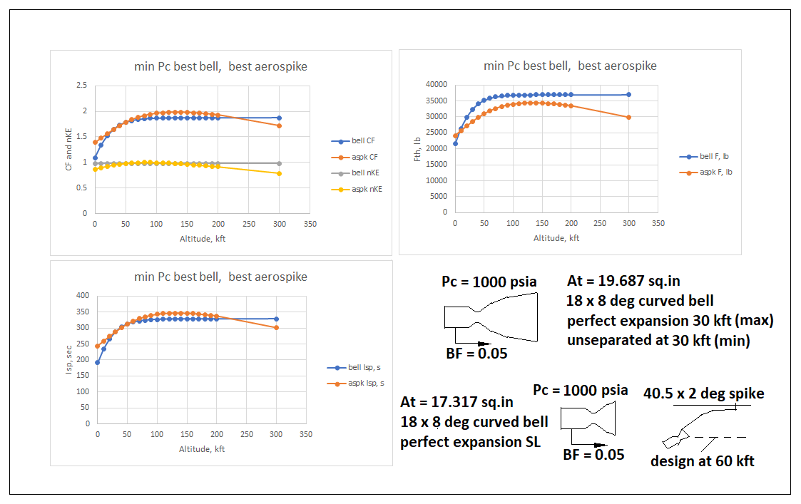
In Figure 16, the same comparison plots are given with both
operating at min Pc = 1000 psia. Bear in
mind these are LOX/RP-1 designs that I arbitrarily roughed out. The “best bell” was sized to perfect
expansion at 30,000 feet so that it could be fired in the open air at sea
level, at full Pc. At min Pc,
it must be at or above almost 30,000 feet in order not to separate. It was sized with Fth = 106,230 lb. The best aerospike was the revised spike with
the supersonic-bell gas generators,
sized for an axial plume boundary at 60,000 feet, and a nominal thrust Fth = 100,000 lb.
There is still performance degradation with the revised
aerospike below fixed-bell levels, while
flying out into vacuum, but it is not
nearly as degraded as with the earlier sonic-only gas generator aerospike
design described above. This improvement
in performance was afforded by the limited supersonic expansion bell on the gas
generator, which limits how adversely-lateral
the plume angle can spread at lowest backpressures. The aerospike itself is a little less extreme
in its initial angle, as well.
That this revised aerospike is a near-optimal design
is confirmed by its specific impulse performance very slightly exceeding the
best fixed bell, from sea level to about
200,000 feet. For ascents, this aerospike might be competitive in terms
of performance, since the specific
impulse advantage in the stratosphere offsets the specific impulse deficit out
in vacuum, as long as it is not used for
too much impulse delivery out in vacuum.
For routine use out in vacuum,
the fixed bell is still better.
The original conclusion above that aerospikes are not
good vacuum nozzles really is confirmed in this update. However,
the vacuum shortfall definitely can be made more modest than was
originally indicated in the sonic-only gas generator version. One does that by fitting a sea level bell
upon the gas generator, allowing a reduction
in initial spike surface angle off of axial.
The mechanism of the fan angle reduction is the direction-confining
action of the modest bell, limiting the
further Prandtl-Meyer expansion angle from there to ambient, and which then also allows higher chamber
pressure.
The higher chamber pressure raises both c* and thrust
coefficient, which in turn acts to raise
specific impulse. The more-limited plume
fan-out angle in vacuum raises the effective nozzle kinetic energy
efficiency, which acts to raise thrust
and specific impulse. Of the two
effects, the fan angle dominates.

Figure 13 – Basic Results for Aerospike with Supersonic-Expanding
Gas Generator

Figure 14 – Detail Results for Aerospike with
Supersonic-Expanding Gas Generator

Figure 15 – Comparison of Best Bell and Best Aerospike at Max Pc
The basic message here is that by sizing the throat areas
correctly, the thrust shortfall evident
even in the stratosphere in Figures 15 and 16 can be eliminated! This will not really change the thrust
coefficient and specific impulse trends!
Those show the revised aerospike (with combined supersonic bell and
free-expansion spike) can equal or exceed the performance of the “best” fixed
bell up to the outer stratosphere (around 200,000 feet), but will inevitably fall short of
fixed-bell performance from the outer stratosphere on out into vacuum!
Those statements are made for a “modest vacuum bell”
design, sized to operate over-expanded
at sea level up to its design perfect expansion altitude of 30,000 feet. From there it operates under-expanded all the
way to vacuum, at the highest expanded-momentum
term available. That design selection is
limited by being able to test fire in the open air without flow separation at
sea level and full power. It cannot be
test-fired at sea level like that, at
min throttle.
The ”full vacuum bell” can equal aerospike performance in
the stratosphere, as indicated in Figure 17, but cannot be operated at sea level. However, note that out in vacuum, even a sea level bell outperforms the
aerospike! Aerospikes are quite simply not good vacuum
engines!

Figure 17 – 3-Way Comparison In Terms of Specific Impulse

Thank you for the analysis.
ReplyDeleteI guess these guys have minimal "aerospike" effects https://youtu.be/EY8nbSwjtEY
Watch for an update. I plan to examine what I suggested in the article as a better design.
DeleteThis is a very surprising conclusion! Why then are aerospike nozzles considered optimal for SSTOs, where average Isp is a critical measure?
ReplyDeleteThis stuff sells technology programs to government labs, that's why. Marketing hype. Aerospikes are really good from the surface to high in the stratosphere. They are lousier than a conventional sea level bell out in vacuum.
Delete