Monday, May 1, 2023

Heat Shields

Updated same day (5-1-2023):  replaced 3 tables embedded in text that did not indent correctly,  with images that are neat and easier to read.

----------------------------

Update 5-8-2023:  Corrected the text adjacent to,  and in Figure 2 itself,  to indicate peak heating occurring before peak gees,  not later.  This was based on models run of Apollo-like objects at LEO entry and escape-speed entry.  

----------------------------

Entry heating is a serious problem for any kind of space activities that require returning something to Earth,  or entering the atmospheres of other bodies that have them.  The “breakthrough” in mitigation schemes came in the early 1950’s when H. Julian Allen and A. J. Eggers realized that blunt shapes endured less heating load.  This enabled the development of ICBM warheads that could survive entry by the mid 1950’s,  and immediately thereafter the development of film payloads returnable from spy satellites.  Shortly after that,  it was used for human passengers returning from orbit in the early 1960’s.   

There are two kinds of heat loads applied to a piece of the surface material of a body during entry:  convective and radiative.  The convective heating is scrubbing by hot gases,  and is more-or-less proportional to speed cubed,  proportional to the square root of the ambient atmospheric density,  and inversely proportional to the square root of the blunt nose radius of the body.  Radiative heating is the heat shining upon the body from something else (the glowing plasma sheath) that is very hot,  and is more-or-less proportional to speed raised to the 6th power.  However,  this is rather insignificant until it suddenly starts to dominate the total heat load at about 10 km entry speeds.  See Figure 1. 

Convective heating is maximum at the stagnation point,  something like factor 3 lower away from stagnation,  but still scrubbed by attached slipstream flow,  and around a factor of 10 lower still,  on surfaces immersed in separated-wake regions.  Radiation heating is strongest at the stagnation point,  but does not decrease as rapidly as convective heating does, around other places on the body.

There are two or three ways that incoming heat may be lost from that same piece of surface material on that entering body.  Heat absorbed within the material may be conducted further inward into interior cooler structures,  and heat may be re-radiated from its hot surface as infrared (IR) radiation,  back to the external environment.  The third involves either of a couple of mass transfer effects.  See again Figure 1. 

For non-ablative materials,  a sacrificial coolant may be percolated through a porous surface material to cool it.  The coolant absorbs some of the heat load,  then boils away,  and this vaporizing mass flow is carried away,  with that heat it absorbed,  in the slipstream.  That is called “transpirational cooling”. 

For ablative materials,  there is a layer within the material that undergoes pyrolysis as its temperature gets hot enough.  Pyrolysis products are the carbonaceous char left behind,  and copious quantities of gaseous species that percolate out into the slipstream.  It takes a “latent heat of pyrolysis” to do this physical transformation,  so the departing gaseous pyrolysis products carry away significant heat.  That is how “cooling by ablation” works.  Depending upon the density of the material,  it may also interrupt (or carry) conduction heat flow inward to the substrate.  Lower density is lower thermal conductivity.

One should be aware of the effects of the “plasma sheath” of the slipstream that is close to the surface of the body,  behind the detached bow shock wave.  This is very hot gas,  hot enough to be ionized to one level or another (ionization being the definition of “plasma”).  Visually,  it glows with incandescence.  Once brightly incandescent at about 10 km/s entry speeds or higher,  it radiates considerable heat that strikes the immediately-adjacent body surface.  This is the mechanism by which the radiation heating term arises,  which is more-or-less proportional to speed raised to the 6th power.  See again Figure 1.

That same effect of ionization increasing with speed affects the transmission of radio waves through the plasma sheath,  starting at speeds well below 10 km/s (nearer 6).   That is the cause of the entry radio blackout intervals.  It affects both radio communications and ground-based radar (which sees the plasma sheath,  but not anymore the solid body inside that sheath),  nor can an on-board radar see the surroundings through that sheath.   

At speeds high enough,  a similar thing happens with respect to infrared (IR) radiation:  the sheath goes opaque to it.  That stops any cooling by re-radiation of IR to the surroundings.  This happens with visible light,  too.  It gets very hard to see through the plasma sheath,  if speeds are high enough.

All of these phenomena are summarized briefly in one place,  in Figure 1.  Be aware that in steady state,  the various heat flows must add to zero,  and that the small differences between very large numbers can have catastrophic effects.  Peak heating numbers during entry are quite extreme. 

Figure 1 – The Phenomena Involved With Entry Heat Shields

Entry is not a steady-state process.  One hits something called the entry interface altitude (where heating first becomes perceptible),  but due to the extremely low densities that high up,  one does not decelerate much at all,  initially.  Neither does the heat load build up,  initially.  Low density affects both. Then the larger atmospheric densities further down,  acting in concert with the still-very-high speeds,  suddenly cause very large deceleration forces (and heat loads) on the body.  They “peak”.

After this,  the body is moving very much slower,  and the deceleration and heat loads drop off,  despite the rapidly-increasing atmospheric densities.  This is shown illustratively in Figure 2.  (Although,  if you come in too steep,  you may hit the surface before the max deceleration and heating can occur.)

There is a simple approximate estimating technique,  first done by H. Julian Allen about 1953,  and declassified circa 1958.  This was originally for fairly-steeply-entering warheads,  and so was formulated as a 2-D Cartesian planar analysis.  However,  if you “wrap” the ranges around the curved Earth,  it still gets you “into the ballpark” for the shallower entries we associate with space vehicles today.  It presumes a simple exponential function representing density versus altitude,  which is adequate for the variation of density at the altitudes where these entry phenomena actually occur.  The results one gets with it clearly show that the max deceleration and max heating pulses are not simultaneous:  peak heating occurs slightly earlier than peak deceleration.  See again Figure 2.

Figure 2 – Transient Nature of Entry  (Corrected 5-8-23)

Not shown is the effective average pressure across the body cross section.  This maximizes at peak deceleration.  Think of it as the force to decelerate the body at the peak deceleration gees (basically gees multiplied by body weight),  spread over the blockage cross section area of the body (P = F/A).  That gets you into the ballpark for the surface pressures seen by the body heat shield.  Peak pressures at the stagnation point might be around factor 2 higher.  The heat shield must be capable of structurally withstanding surface wind pressures of that magnitude. 

So not only peak heating rate per unit area capability,  but also max survivable pressure capability,  are critically important to selecting the right heat shield material.  The pressure effect was mostly unrecognized early on,  but became quite important for escape-speed returns to Earth,  and for entries at other planets directly from interplanetary trajectories.

Old NASA data

I found online a slide presentation overview of what NASA knows about heat shields.  This was the Paolo Santini Memorial Lecture,  given by Ethiraj Venkatapathy,  as indicated by the notations in Figure 3.  It mentions some knowledge that precedes the formation of NASA in 1958,  and does not go into the very extensive military warhead heat shield efforts of the early 1950’s.  It does mention an expedient tried on the V-2 rocket to keep the warhead from “cooking off” prior to target arrival.  It also mentions the metallic and coated-metallic surfaces tested hypersonic on the X-15 in the 1950’s and 1960’s.  There are similar heat protection issues with metal-skinned missiles flying at high-supersonic to hypersonic speeds.

The military warhead efforts in the Figure 3 data are only summarized as “wrapped in silica phenolic” circa 1958.  That material is a very good ablator,  if rather heavy and expensive,  that is still often used in solid rocket (and modern ramjet) nozzle construction for missiles.  It is very closely-related to the material finally used for the Mercury capsule heat shield:  fiberglass cloth-reinforced phenolic resin shingles,  bonded together and to a substrate. 

A different scheme was attempted successfully for the Gemini capsule:  a silicone-RTV elastomer loaded into the hexagonal cells of a fiberglass honeycomb.  This basic elastomer-in-honeycomb notion is clearly an ancestor of the Avcoat used on Apollo.  While still heavy for Gemini,  the micro-balloons in the Avcoat used on Apollo reduced its density (to 0.51 g/cc) and weight substantially.  An even lower-density form (about 0.25 g/cc) designated SLA-561V was used on the Mars Viking landers.  See again Figure 3. 

A different scheme was used for the Pioneer-Venus and Galileo probes,  because of the vastly-higher peak heating loads and surface pressures.  This was a tape-wrapped carbon-phenolic composite material.  It was very capable,  but also heavy and expensive.  It did show the advantage of carbon materials as ablators.  So did the Genesis probe,  which used a carbon-carbon composite as ablator,  over a low density carbon insulator (basically a carbon fiber felt). See again Figure 3. 

Mars Pathfinder used a Viking heat shield,  while the Stardust probe used an initial form of the then-new Phenolic-Impregnated Carbon Ablator (PICA) heat shield.  See again Figure 3.  

Figure 3 – A Overview of NASA Heat Shield Knowledge

What got left out of this list were the Space Shuttle heat shield materials:  the two different types of low-density refractory ceramic tiles,  the ceramic cloth insulation blankets,  and the carbon-carbon composite nose cap and aerosurface leading edges,  which were slow ablators at entry conditions from low Earth orbit (about 7.9 km/s at entry interface).  The low-density ceramic tiles served the cooling-by-reradiation function,  and provided the low thermal conductivity effect,  due to their high void space fraction reflected in their low densities.  That last mostly cuts off conductive heat flow into interior structures,  allowing aluminum substructure,  but the material is also inherently weak and fragile. 

Discussion of all the ablative materials

A closer reading of the history of Project Mercury,  reveals that the initial choice was a beryllium heat-sink heat shield,  which actually flew on some of the early unmanned suborbital tests.  By the time of the first manned suborbital flight in 1962,  the glass-phenolic ablative shield was “standard”,  and it proved adequate for entry from low orbit.  It’s still quite heavy,  but was made a bit less expensive by substituting glass fiber cloth for silica fiber cloth. 

The silica version is the better ablator,  but the glass version was adequate for this design.  A sample cut from an ablated Mercury heat shield is shown in Figure 4.  One can see the glass cloth layers in the material,  especially near the pyrolysis zone.  It is the phenolic resin pyrolyzing that creates the carbon char layer.  This is definitely a fiber-reinforced composite material,  with the resin reinforced by the layers of woven glass cloth.  These need to be oriented so that surface wind shear forces do not pry apart the layers of the reinforcing cloth (the same restriction is true with silica phenolic in missile nozzles).  

Figure 4 – The Glass-Phenolic Ablative Used for Mercury Capsules

The Gemini heat shield material was a silicone elastomer injected into the cells of a fiberglass honeycomb,  and cured there.  This is quite the different material from the Mercury heat shield,  but is clearly related in its fundamental concept to the Avcoat-in-honeycomb used on Apollo.  It is also a reinforced composite material,  with the cured silicone elastomer being reinforced by the walls of the small cells of the honeycomb.  The silicone was an ambient-curing elastomer from Dow Corning:  DC 235. 

A sample cut from an ablated Gemini heat shield is shown in Figure 5.  There is a whitish surface atop the black carbonaceous char.  This is mostly molten silica product made from oxidized silicon coming from decomposition of the silicone elastomer,  which elastomer also forms the carbonaceous char.  Molten glass from the fiberglass honeycomb is a small part of this whitish surface material,  which effect is also seen as some whitish flecks on the surface of the Mercury heat shield sample. 

This material is not only heavy,  it is also rather expensive,  because of the hand labor involved.  Each cell must be “hand-gunned” full of the elastomer,  and there are hundreds of thousands of them on a heat shield of any significant size. 

Figure 5 – The Silicone-RTV in Honeycomb Ablative Used for Gemini Capsules

The next step forward with the filled-honeycomb-cells composite concept is the Avcoat-in-honeycomb used on Apollo,  and in one or another form subsequently.  The form used on Apollo was Avcoat 5026-39G,  which was an epoxy-novalac resin filled with both quartz fibers and phenolic micro-balloons,  hand-gunned into the hundreds of thousands of cells in a phenolic honeycomb,  bonded to the substrate surfaces of the vehicle. 

The epoxy-novalac resin (and the phenolic of the phenolic honeycomb) provide the source of the carbonaceous char.  The composite reinforcement is from the walls of the small honeycomb cells.  The quartz fiber filler in the resin provides a source of molten silica for densifying the surface of the char,  as well as a fiber-strengthening function for the virgin material and its char.  The phenolic micro-balloons provide the void space to lower the density rather significantly,  and thus the weight of the finished heat shield.  They also provide a compressive strengthening function,  similar to the aggregate in concrete. 

This material proved adequate in terms of heat load capacity and erosion resistance for Apollo returning from the moon at just about 10.9 km/s speeds at entry interface.  It is rated for 600 Watts/sq.cm,  at a significant fraction of an atmosphere of surface pressure.  A sample cut from an ablated heat shield is shown in Figure 6.  There is enough silica whitening to render the black char’s surface a light gray color.  One can very easily see the small honeycomb cells.

Figure 6 – The Avcoat-in-Honeycomb Ablator Used for Apollo Capsules

The same basic material,  rendered even lower in density (presumably with a higher micro-balloon content) is the SLA-516V material used for the Mars Viking lander heat shield. 

A very close variant of the Apollo material was initially chosen for the new Orion capsule,  designated Avcoat 5026-39HC/G,  which is the same epoxy-novalac resin filled with the same quartz fiber and phenolic micro-balloons,  hand-gunned into the cells of the same phenolic honeycomb.  There are more than 300,000 such cells in the heat shield of an Orion,  so the labor to hand-gun this stuff is very large and expensive,  and the quality of the results varied among the various individual “gunners”.  This heat shield flew on the first Orion flight test EFT-1,  and was very successful. 

To address the labor expense and variability,  a variation was flown on the second Orion flight test,  which was the first Artemis program flight EM-1.  For this heat shield,  the Avcoat was made in tiled blocks of cured filled resin,  without the honeycomb.  300 of these tiled blocks were bonded to the capsule substrate for that flight.  Without the reinforcing effect of the honeycomb,  this was less successful than hoped.  The erosion rate was higher and more variable than expected,  with charred material coming off erratically in larger discrete chunks,  instead of steady loss of fine char granulate eroding away.  Apparently,  deleting the honeycomb reinforcement was a design mistake!  This issue will have to be addressed before flying the first manned Artemis mission,  EM-2.

The success of the Galileo and Pioneer carbon-based heat shields,  plus the success of the carbon-carbon composites of the Space Shuttle nose cap and aerosurface leading edges,  led to serious development efforts toward carbon ablators.  Those culminated in NASA’s PICA material,  subsequently improved and used by SpaceX as PICA-X,  on its Dragon capsules. 

The basic notion ended up as a carbon fiber preform of very high void fraction,  impregnated with a phenolic resin that had lots of bubbles in it,  once cured.  The carbon fibers were the reinforcement to a composite material,  in which the phenolic was the matrix.  The phenolic would form a char under pyrolysis,  and together the carbon fibers and the carbon char would erode very slowly.  The bubbles in the phenolic,  plus the fact that it incompletely filled the void spaces in the preform,  led to low densities in the 0.25 to 0.28 g/cc range. 

This material would handle rather substantial heat loads at modest ablation rates,  survive at significant pressures,  and was very lightweight as heat shield materials go.  The variations involve exactly how you make your carbon fiber preform,  and exactly how you go about creating the bubble voids in the phenolic.  Those variations do significantly impact the heat load capacity,  density,  and strength.

NASA’s original version used a carbon fiber preform from a company known as FiberForm.  It was a felt of high porosity fully carbonized (and thus rigid),  using certain Rayon fibers as the carbon fiber source.  It would handle over 1000 Watts/sq.cm of heat load,  at around half an atmosphere pressure. 

Similar carbon fiber felts are available from other manufacturers,  and some of those are not fully carbonized,  leaving them flexible enough to be conformable.  These variations affect performance significantly,  usually leading to unacceptably-reduced char erosion rate performance as a heat shield.  The biggest problem with the NASA version of PICA has become the unavailability of suitable Rayon fiber due to environmental concerns in recent years.

SpaceX has selected a version they call PICA-X (from three possible variants) for use on their Dragon space capsules.  I have been unable to determine exactly what they did,  but they have the rigid carbon fiber preforms that they need,  seemingly made in-house at SpaceX.  They make their own PICA-X tiles from them,  and bond these to the capsule substrate.  I was unable to locate details,  but the talk is that the SpaceX PICA-X material is easier to manufacture,  and far less expensive (by a factor of 10),  than NASA’s original PICA,  while equaling (or slightly exceeding) the ablation performance of the original.

NASA’s original PICA was used in tile form on the Mars MSL lander (Curiosity rover).  Neither that application,  or any of the SpaceX Dragon capsules,  have shown a problem with tiles coming off.  All in all,  PICA-X seems to be a very reliable material,  apparently without the Rayon availability problems of the original PICA.  That is not to say that future variants could not be even better. 

Figure 7 shows a sample of PICA being tested in the arc-jet tunnel,  at entry-like conditions.  The top of the char layer is soaked-out to white-hot incandescence. 

Figure 7 – A PICA Low-Density Carbon Ablator Being Arc-Jet Tested


The best heat shield ablatives currently available

Discussion of refractory ceramics

NASA’s experience with refractory ceramics (which they term “insulative”,  although not all ceramic tiles are) derives largely from 30 years of experience with the Space Shuttle.  Their low density tiles (around 90% void space) were made of silica,  alumino-boro-silicate,  and alumina fibers.  The alumino-boro-silicate fibers were from Nextel,  makers of fire curtain cloth.  All this stuff is limited to returns from low Earth orbit.  High energy orbit entries,  and entries at or above escape,  simply require ablatives,  period. See Figure 15 in the addendum below,  obtained from that NASA presentation found on-line. 

These tiles ended up densified somewhat at the bond side,  and over time with two different dense coatings on the exposed side,  in two colors.  Windward side tiles were tinted black to raise emissivity above 0.8 for efficient re-radiation.  Leeward side tiles were tinted white,  because high emissivity was not needed,  but on-orbit passive vehicle thermal control was.

Initially,  the Shuttle leeside was all white tiles.  Later on,  this was replaced by  flexible thermal blankets of two kinds,  one more heat resistant,  except on the higher-risk OMS pods.  These blankets proved no more durable than the tiles,  but required less labor to install correctly.  They did present their own problems with edges protruding up,  and stitching and seams wearing out quickly. 

Because these tiles (and blankets) were very insulative (very low thermal conductivity),  heat conduction into the substrate structures was minimized enough to permit the use of an aluminum airframe construction.  That was required to make the Shuttle design feasible at all.

The nose cap,  and wing and tail leading edges,  endured temperatures too high for even the black-surfaced ceramic tiles,  and were made instead of carbon-carbon composite-based ablative structures.  The material was a carbon cloth impregnated with phenolic resin,  and furnace-pyrolyzed to an all-carbon composite structure.  This was repeatedly soaked in furfuryl alcohol and hot-dried,  to densify the composite and even-out its properties.  Clearly,  this stuff is not cheap or easy. 

The composite has a high density and thermal conductivity,  but the stagnation zone is a thin line or small patch,  on a much larger part.  It gets very hot near stagnation (around 3000 F during a 7.9 km/s entry).  Heat conducts and re-radiates internally to cooler regions of the part,  where steels can be used to secure it.  Being black,  the exterior surface,  once hot,  re-radiates efficiently to the environment.  Meanwhile,  a little of the composite ablates away with each flight.  After a few flights,  you must replace it,  or else risk loss of craft and crew,  when the thinned part collapses under entry airloads.

Steel and titanium structures supporting and attaching the carbon-carbon composite material,  is how the nose cap and leading edge structures were made.  These required internal insulation to interrupt radiant heating of the titanium portions,  and (more importantly) radiant heating of the aluminum airframe structures to which these parts were bolted.  Clearly,  proper design is not simple!

The exposed-side surface densification (and colorant) coatings were initially a glassy material (termed “reaction-cured glass” or RCG) applied to the surface,  but which did not penetrate into the porous insulative low-density tile structure.  These proved rather vulnerable to impact damage.  They were replaced by a different densifying (and colorant) surface coating (termed toughened uni-piece fibrous insulation or TUFI),  that did penetrate into the low-density tile structure.  These proved much more resistant to impact damage.

Another ceramic heat shield NASA has been working on is known as TUFROC,  for Toughened Uni-piece Fibrous Oxidation Resistant Ceramic,  intended for use on the unmanned X-37B currently operated by the US Air Force.   This craft is a small derivative of the Space Shuttle.  Whether the TUFROC tile system has ever actually flown in it,  is not very clear,  but it may have flown as protection for the leading edges.  What USAF does on-orbit with that craft is not disclosed to the public.  Little is known.

According to what NASA has disclosed,  the TUFROC design calls for two pieces mechanically tied together.  There is some sort of dense,  hard ceramic cap,  overlaying a lower-density porous fibrous ceramic interior.  They did not disclose how these tiles are mounted to the airframe,  but it is most likely similar to what was used on the Shuttle:  expansion pads and spacing bars,  all glued down with RTV silicone to the airframe,  and the tile glued down with RTV silicone to that substructure.

Whatever the TUFROC capping material is,  it can take much higher temperatures (reportedly 1922 K = 3000 F) than the aluminosilicates used on the Shuttle (2000 F rating).  Whatever the fibrous substrate is,  it can also take higher temperatures than the aluminosilicate Shuttle tile material.  NASA does not say what it is or what it can take,  but consider that the backside temperature of the dense cap material will not be that much reduced from the exposed face temperature,  since the dense material would have a high thermal conductivity. 

NASA has been researching the new ultra-high-temperature ceramics (UHTC).  These are high-density materials of high thermal conductivity,  so that a similar scheme to the Shuttle carbon-carbon-composite parts must be used in order hang onto such hot parts.  This technology must be viewed as very immature. 

NASA has also been looking at future ablators.  These include advanced PICA-like ablators,  something called “graded ablators” (which likely has to do with layering different materials together),  conformable PICA (which has recently been found to ablate faster than rigid PICA),  fully-flexible forms of PICA and something called SIRCA,  3-D woven carbon materials,  and a replacement for carbon phenolic.  None of these are ready-to-apply technologies.  (But they could become ready!)

SpaceX is using some sort of tiled heat shield on its new “Starship” vehicle.  It is not yet clear what those tiles are.  They are black for efficient re-radiation,  and they are located on Starship’s windward surfaces during entry.  I have seen them called both “ablative” and “ceramic” in the talk online.  I have even seen one suggestion that they are TUFROC,  although NASA has given that technology to Boeing,  a serious competitor to SpaceX.  If the PICA vs PICA-X history is any guide,  it seems likely the SpaceX tiles are something developed and manufactured in-house at SpaceX.  They could well be an adapted form of the PICA-X ablator.  We just do not yet know.

The best refractory ceramics available

Discussion of re-radiatively-cooled metals

The notion of using metal surfaces exposed during entry goes back to the 1930’s and 1940’s,  long before the heating issues during entry were understood.  The basic notion is to let the skin get hot,  then let it re-radiate thermally to the environment.  There would be some (or perhaps lots) of conduction into cooler structures inside.  The design must establish an equilibrium where the re-radiative (and conduction) heat flows balance the entry heating encountered. 

There is some merit to that notion,  but as it turns out,  even from low Earth orbit,  only on leeside surfaces where the entry heating loads are far lower.  It also has merit for high-supersonic and low-hypersonic flight down in the atmosphere (usually higher in the stratosphere where the densities and heating loads are lower).

There are two things of critical importance for this notion:  how hot can the surface get,  and how efficiently can it thermally re-radiate?  The effective temperature of the surroundings is a part of that efficiency,  but it is primarily controlled by the surface’s spectral emissivity,  a number between 0 and 1.  Surfaces with high emissivities in the IR band re-radiate thermally very efficiently.  Those with low emissivities do not.  The emission is far better at higher temperatures,  that being controlled by a temperature to the 4th power term in the radiated energy equation.  See Figure 8.

Figure 8 – Thermal Emission from Hot Surfaces

As the figure indicates,  there’s not much re-radiation to be had down near 1000 F temperatures.  Accordingly,  the emissivity makes only a small difference there.  At around 1500 F,  the amount of re-radiation available is becoming quite significant,  and the emissivity makes a clear and compelling difference.  The closer to 2000 F we can operate,  the more effect we can get out of this kind of cooling,  but we really have to have a high emissivity to obtain it. 

You don’t get that high emissivity with an ordinary paint.  At surface temperatures nearer 1500-2000 F,  such a paint would be burnt away.  It takes some sort of metallurgical surface treatment or coating to achieve this,  especially since many metal alloys are quite shiny-silvery in color,  bespeaking quite the low emissivity.  The more reflective the surface,  the lower the visual emissivity,  and the lower the thermal (IR) emissivity is likely to be.  The visual band (0.3 to 0.7 microns wavelength) is just not that far from the infrared bands (0.8-14 microns).

What we are looking for are metal alloys with high max service temperature limits at or above 1000 F,  that still have significant strength when soaked out that hot,  and that can be shaped and welded without too much trouble.  The 1000 F value rules out aluminums (max 350-400 F),  titaniums (max 750-800 F,  and mild carbon steels (max 750-800 F).  That leaves as places to look:  the low-alloy and intermediate-alloy steels,  the stainless steels,  and the high-temperature alloys (iron and other bases). 

Of the low-alloy steels available,  Figure 9 would suggest only D6AC and AISI grades 4140,  4340,  and 8740 as candidates.  These have very nice high strength hot,  but are limited to temperatures in the low end of the attractive IR emissions range:  1000-1100 F.  All would need metallurgical surface treatment. 

Figure 9 – Data For the Low-Alloy Steels

The intermediate-alloy steels of Figure 10 are not very attractive,  being limited to service temperatures only in the 800-900 F range.  “Chrome-moly aircraft steel” (5Cr-Mo-V) is one of these.  

Figure 10 – Data For the Intermediate-Alloy Steels

The stainless steels offer more promise.  These are formable and machineable,  and weldable if one takes care to chose the weldable grades,  usually bearing an L suffix.  They are work-hardenable,  but anneal back to the soft state upon heating.  Strengths are not all that high,  especially hot.  For long-term loading,  creep-rupture effects dominate over short-term strength.  See Figure 11.  

Figure 11 – The Stainless Steels (Both Austenitic 300’s and the Martensitic/Ferritic 400’s)

If service temperatures to about 1600 F are acceptable,  both 316 and 347 stainless are easily available.  The 316L grade is weldable.  Its hot strength is only about 25 ksi tensile ultimate,  which may be too low for a structural skin application on a windward surface.  Strengths are higher, in the 75-80 ksi range,  if you can keep them cooled near only 400 F,  with a refractory or ablative covering.  Grade 304 would be comparable in strength,  and equal in service temperature rating (1600 F),  driven by oxidation (forming surface scale).  The 304L form is weldable.  304/304L also serve well at cryogenic temperatures.

If you need to go hotter,  then grade 310 can take you to 1800 F at 12 ksi strength,  with an oxidation limit of 1900 F.  It is not as available as 304,  316,  and 347.  I am unsure if it is a weldable grade.

The high temperature metals include iron-based,  nickel-based,  and cobalt-based alloys.  The data on these are given in Figures 12 and 13.  At 1400 F,  Hastelloy B has good strength and is at its oxidation limit,  although there are strength data to 1600 F.  A stronger candidate at 1400 F is Waspalloy,  well within its oxidation limit. 

At 1600 F,  Inconel 625,  Inconel 718,  M-252,  and Udimet-500 all have significant strength,  and are at or under their oxidation limits.  There is also Rene 41 (proposed for the X-20 Dyna-Soar).  Rene 41 has process problems reported (long exposures weaken it),  but it has strength reported at 1800 F,  despite being above its oxidation limit there. 

At 1800 F,  there is L-605,  which is within its oxidation limit. 

At 2000 F,  there is N-155,  which is not within its oxidation limit,  and Alloy 188,  which is.  Alloy 188 has the highest oxidation limit at 2100 F of any of the high-temperature metals.  It will go hotter than any of the stainlesses,  and has higher strength that hot,  than the stainlesses do at their limits. 

Figure 12 – Strength-Temperature Data for the High-Temperature Metals

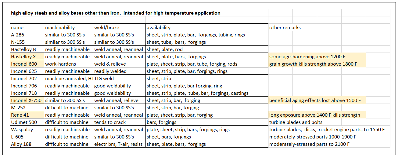
Figure 13 – Machineability and Weldability Data For the High-Temperature Metals

The best re-radiatively-cooled metals

The oddball case of the X-15A-2

The famous X-15 rocket plane was first flown in 1959,  and completed 199 missions by the time it was taken out of service in 1968.  There were 3 vehicles:  X-15-1 bureau number 56-6670,  X-15-2 bureau number 56-6671,  and X-15-3,  bureau number 56-6672.  X-15-3 was destroyed in a fatal crash.  X-15-2 was badly damaged in a crash landing,  and subsequently rebuilt as the X-15A-2,  with external propellant drop tanks.  Both the X-15A-2 and X-15-1 are now on public display.

This craft had Inconel X-750 skins over titanium internal structure,  and had a very black,  highly-emissive metallurgical surface coating.  These skins were convectively heated by low hypersonic flight,  and were cooled by re-radiation of IR thermal energy.  This sufficed to about Mach 5.5-to-6 speeds.  

To go beyond Mach 6,  the X-15A-2 was coated with a catalyst-cured silicone rubber ablative,  designated MA-25S,  which also saw use on the Space Shuttle,  and is a protective coating in common aircraft use.  It is rated to about 700 F,  and will char slowly while surviving 2000+ F fire exposures for several minutes.

There are two forms:  a Type I sprayable,  for area coverage,  and a Type II that is solids-loaded and trowelable,  for small areas,  or making repairs to the Type I.  This stuff is rather pink in color,  and resembles the pink rubber of a pencil eraser.  As it turns out,  there is a fire and explosion danger,  if liquid oxygen is spilled upon this material. 

The X-15A-2 was coated all-over with sprayable Type I MA-25S,  except for the wing,  tail,  and fin leading edges,  which were coated in the moldable Type II.  Because of the liquid oxygen risk (and the test pilot refusing to fly a pink airplane),  this ablative coating had a white sealer coat of paint applied to it.  I am unsure what paint was used,  but I suspect it was some sort of ceramic high-temperature paint. 

Multiple flights were made,  with and without the external tanks,  culminating in the speed record-setting flight to Mach 6.7 at 19.3 miles (about 100,000 feet).  On that flight,  the craft carried a scramjet test article on its ventral fin stub.  See Figure 14.  The scramjet article is mounted to the forward end of the ventral fin stub.  It simulated a cone-spike inlet geometry,  but was not an actual engine.  

Figure 14 – Launch of X-15A-2 with Scramjet Article From B-52 Carrier Plane

There was considerable shock-impingement and shock-interference heating problems due to the presence of the scramjet under the tail of the airplane.  NASA TM-X 1669 indicates that heating was locally increased by a factor of 9 in the impingement zones,  and by a factor of 7 in the interference zones.  On the fin stub and under the tail,  the silicone ablative was completely stripped away,  and numerous holes burned through the Inconel skins,  some of them quite large.  Had the exposure continued even a little longer,  the aircraft might have been fatally damaged.

The silicone ablative was seriously charred in other areas,  most notably the wing,  tail,  and fin leading edges.  Anywhere that there was a local hot spot for any reason,  the white coating was lost,  and the underlying silicone ablative was damaged.  Canopy framing and instrumentation probes were other locations showing local hot spot damage.

An informed speculation says that the white paint color may have impeded re-radiation by low emissivity,  leading to higher surface temperatures than the experiences with the black metal would suggest.  However,  there was nothing about the metal re-radiation or the silicone ablative that could have resisted the shock-impingement and shock-interference damage!  The key for future designs is to eliminate those effects.  That requires very careful aerodynamic design for locating tail surfaces,  and the presence of no parallel-mounted nacelles (like the scramjet article) at all!

Addendum

Figure 15 was obtained from the NASA presentation found on-line regarding the Shuttle thermal protection system (TPS).  It pretty much makes the case (very visually!) about where reusable refractories may be used,  and where ablatives must be used,  for entry heat protection!  This is pretty much based on the 2000 F max surface temperature limitation for the low-density ceramic Shuttle tiles. 

One point:  the earlier space capsules (Mercury and Gemini) entered at conditions similar to the Space Shuttle,  in terms of the altitude-velocity “space” depicted in the figure.  Also bear in mind that locations on the Shuttle that endured stagnation-zone heating were not tiled,  they were protected by the carbon-carbon composite slow ablative.   Ballistic coefficients would have been crudely comparable for the Shuttle and those capsules.  

Some of the probe designs for returning from the far solar system would have had smaller ballistic coefficients,  and a small sample-return capsule doing a free return from Mars would have similar  ballistic coefficients as well as similar extreme velocities.  That is really why the trajectory lines for Mars return and far solar system return are so close together.   A manned vehicle coming back from Mars will more likely have a higher ballistic coefficient and a less extreme return velocity.  Its curve would be to the left and somewhat below the Mars return line shown in the figure.

What makes the stagnation zone problem so difficult,  is that there is a limit to the heat rate that can be re-radiated from a “black” surface,  that is determined by just how hot you can let that surface get (in the Shuttle tile case:  2000 F).  The stagnation zone heating rate even from only low Earth orbit can be (and in most cases is) very much higher than the possible re-radiation heat rate.  With the conduction inward mostly cut off by the low density and low thermal conductivity of the ceramic tiles,  re-radiation was the only way to reject the applied convective loading.   They had to be equal!  That limits speed.

However,  away from those stagnation zones at the nose cap and leading edges of the Shuttle,  heating rates are crudely a factor of 3 lower,  which is why the black tile solution was feasible for the windward-side surfaces on the belly,  and the bottoms of the wings.  On the leeward-side surfaces,  heating rates are crudely a factor of 10 lower than stagnation,  which is why the leeward-side tiles could be the inefficiently-re-radiating “white” color that allowed passive thermal control on-orbit. 

For a small object with a very low ballistic coefficient,  stagnation heating rates are somewhat lower,  because the peak deceleration and peak heating occur higher up in the lower-density atmosphere,  if the entry angle is shallow.  If the object is also very,  very blunt (large “nose” radius),  that also lowers stagnation heating.  For such an extremized case,  “black” shuttle tile with a 2000 F limit could be used to protect even the stagnation zone.   Steep entry angle easily negates this.

The point here is that the lines on the figure representing the various entry trajectories can vary somewhat with varying ballistic coefficient,  which is a function of object size (or mass).  The red line dividing “reusable TPS” from “ablatives only” can move quite a bit with varying ballistic coefficients and bluntness,  and significantly if low-density ceramics with higher temperature limits become available.  The NASA figure indicates limits which have been “typical” up to now,  not “cast in stone” in perpetuity. 

Figure 15 – Figure From NASA Presentation Showing Entry Heat Shield Choices

References consulted but not formally cited

Agrawal and Chavez-Garcia,  “Fracture In Phenolic Impregnated Carbon Ablator”,  paper given at the 42nd AIAA Thermophysics Conference,  Honolulu,  HI,  June 2011.

Ethiraj Venkatapathy,  “Ablators:  From Apollo to Future Missions to Moon,  Mars,  and Beyond”,  the Paolo Santini Memorial Lecture,  given at the 70th International Astronautical Congress,  Washington,  DC,  October 2019.

Panerai,  et. al.,  “Analysis of rigid and flexible substrates for lightweight ablators based on X-ray micro-tomography”,  manuscript found on-line via Elsevier,  dated 2016.

Nowlin and Thimons,  “Surviving the Heat:  The Application of Phenolic Impregnated Carbon Ablators”,  Conference Session B9,  paper number 3131,  University of Pittsburg Swanson School of Engineering,  dated 2013.

Poloni,  et. al.,  “Carbon ablators with porosity designed for enhanced aerospace protection”,  international paper financed by the Swiss National Science Foundation pertinent to project 200021_160184.  No presentation or publication date given,  but ref. 1 dates to 2020.

Rodriguez and Snapp,  “Orbiter Thermal Protection System Lessons Learned”,  AIAA paper 2011-7308,  AIAA Space 2011 conference and exposition,  Long Beach,  CA,  2011.

Sylvia Johnson,  “Thermal Protection Materials:  Development,  Characterization,  and Evaluation”,  presentation at HiTemp2012,  Munich,  Germany,  2012.

Watts,  “Flight Experience with Shock Impingement and Interference Heating on the X-15A-2 Research Airplane”,  NASA TM X-1669,  October 1968.

MA-25S Product Data Sheet,  labeled as coming from “Thermal Protection Products”,  no date given.

Mil Hndbk 5C,  “Military Standardization Handbook:  Metallic Materials and Elements for Aerospace Vehicle Structures”,  Sept. 1976.

“High Temperature Characteristics of Stainless Steels”,  a designer’s handbook series no. 9004,  distributed by the Nickel Development Institute (NiDI),  and produced by the American Iron and Steel Institute (AISI), no date given.

Related Articles

I have also posted a number of related articles on this “exrocketman” site.  Use the navigation tool on the left side of this web page to find them quickly and easily.  All you need (I suggest jotting them down) is the title and posting date,  to use the navigation tool.  Click on the year,  then on the month,  then on the title,  if more than one article was posted that month. 

Early High-Speed Experimental Planes, 3 July 2022

About Hypersonic Vehicles, 1 June 2022

On High-Speed Aerodynamics and Heat Transfer, 2 January 2020

Heat Protection Is Key to Hypersonic Flight, 4 July 2017

Shock Impingement Heating Is Very Dangerous, 12 June 2017

Entry Heating Estimates, 1 April 2020

Thermal Protection Trends For High Speed Atmospheric Flight, 2 January 2019

Low-Density Non-Ablative Ceramic Heat Shields, 18 March 2013

BOE Entry Analysis of Apollo Returning From the Moon, 21 January 2013

“Back of the Envelope” Entry Model, 14 July 2012


Tuesday, April 25, 2023

Starship/Superheavy Flight Test

There are three photos of the SpaceX “Starship/Superheavy” vehicle taken during the recent test that terminated in an explosion.  They are very informative. 

In the first one at liftoff,  look at the color and character of the "smoke" cloud.  That's not smoke,  it is dust,  and not very fine-grained,  either,  or it would have billowed up a lot higher.  Combine that with the reports of concrete blocks coming down multiple city blocks away,  and sand coming down 6 or more miles away,  and you understand that what you are really looking at,  is the excavation debris being flung out by the rocket blast as the launch stand is being destroyed for lack of a flame deflector.  See Figure 1.

Figure 1 – A Photo Taken Right At Liftoff

The other two photos show two separate things quite clearly: 

(#1) Yes,  there was vented methane streaming down the side of the vehicle.  It caught fire and base-burned with wake air around the engines,  which plays merry hell with the control wiring and the plumbing on those engines!  That burning methane also entrained onto the engine plumes as subsonic flaming sheaths around the supersonic plumes.  You can tell by the bright yellow color and the wavy nature that this is a subsonic fuel-rich flame. 

(#2) There are supersonic plumes encased in subsonic flame sheaths that point straight aft (from the undamaged engines),  and there are some supersonic plumes sheathed in subsonic flame jetting out to the side,  well off-axis.  Those are coming from badly-damaged engines that are not shut down.  I can see at least 3 of these in the photos.  They represent forces that act to spin the vehicle end-over-end. 

See Figures 2 and 3.  And note:  there is a misalignment between vehicle axis and main plume direction,  indicating the vehicle is not aligned with the slipstream,  by something near 10 degrees.

Figure 2 – A Photo Taken In Flight Before The Vehicle Tumbled

Figure 3 – Another Photo Taken In Flight Before The Vehicle Tumbled

Shortly after these two in-flight photos were taken,  the vehicle went completely out of control,  tumbling end-over-end about 4 times before the self-destruct signal was sent.  In the video footage of the tumbling vehicle,  one can see that the vehicle is no longer straight,  it is bent right at the stage point,  by something near 5-10 degrees.

Informed speculations: 

(#1) Odds favor that some of the concrete block debris chunks hit and badly-damaged multiple engines at ignition and during liftoff,  as the rocket blast excavated that huge hole.  Loss of engines reduced vehicle thrust,  and (more importantly) those damaged engines shedding lateral streams added very large side forces at the rear,  which eventually overcame the thrust vectoring control of vehicle attitude.  Which is why it eventually spun end-over-end.

(#2) It's not yet bent at the staging joint in these views (the photos in Figures 2 and 3),  but I saw the two stages bent out of alignment by around 5-10 degrees in the video footage of the spinning vehicle.  Once the vehicle gets broadside-enough to the supersonic slipstream (about Mach 2 at about 100,000 feet),  the dynamic pressure is around 65 pounds per square foot.  That pressure acting on multiple thousands of square feet of broadside area is way more than enough to bend very thin stainless steel structures.  The weakest point is where the two stages are clamped together,  which is right where it bent out-of-line.

My own observations about this incident:

(#1) SpaceX already knows a lot more about what happened than they are saying in public.  Musk's public admission that they should have had a flame diverter is a hint of that.  This test flight would have gone a LOT BETTER had they had one,  and they know it.

(#2) SpaceX is very likely in trouble again with the FAA,  because the debris that was flung,  was flung much farther than the estimated debris risk distances in the environmental impact documents,  upon which their launch license depended.  That would not have happened if they had had a flame diverter,  and they (and now the FAA) know that,  too.

(#3) FAA will likely not grant another launch license,  until they are shown just how “bad top-level management decisions” (like launching such a giant rocket without a flame diverter) can be avoided within SpaceX.  I'm talking about Musk,  not Shotwell.  She knows better.  He apparently does not,  or else does not care what damage he might cause.  And the FAA now knows that,  too!

(#4) That should give SpaceX plenty of time to install and properly test a flame diverter.  Any few-seconds-long static test of the Superheavy booster can serve to test that flame diverter.  And thus show the suppression of unintended debris-flinging. They don't need a launch license to do that.  But until they do that (and get it right),  they should not fly again.  Why?  Because the collateral damage risk is unjustifiable,  and we have now all seen that.  And I think the FAA now understands that,  too.

Final remarks:

Don’t get me wrong.  I want to see this vehicle fly and SpaceX succeed.  They just need to do it right.  Public safety is at risk.  

---------------------

Update 7-7-2023:  I have since seen in some of the liftoff video footage,  chunks of concrete and steel flung up alongside the rocket,  appearing out of the dust cloud,  and moving at least halfway up toward the nose.  That is very suggestive that the inoperative engines (and maybe some operating engines) were damaged by flung debris chunks at ignition.  

It is also possible that there was damage to the end of the propellant tankage or plumbing,  causing a larger-than-usual amount of methane to be base-burning around the engines and sheathing the supersonic plumes in subsonic flame.  That plume appearance was very unusual,  to say the least.  Just more proof that launching without a deluge flame diverter was an extremely stupid decision

I think the 41 second delay between sending the destruct signal,  and the actual destruction of the tumbling vehicle,  is a substantial indication that the destruct system failed to function.  During those 41 seconds the tumbling vehicle was descending rather sharply into denser air,  where the wind load forces finally broke it up.  

I saw a low of out-of-control rockets destroyed in exactly that way in the 1960's,  along with a lot of others destroyed by the destruct systems.  You can pretty much presume that anything that explodes before it tumbles was a self-destruct for going off-course.  Anything that just suddenly tumbles and explodes,  you can pretty much presume broke up due to air loads before they could send the destruct signal.  

-------------------

Tuesday, April 11, 2023

Classified Intelligence Leak

US intelligence officials are scrambling to contain the damage and find the source of a fairly-serious revelation of classified intelligence information related to Russia’s war in Ukraine.  This is causing all sorts of problems,  as one might well expect.  So far,  everyone seems rather clueless about who did this release (which is a felony-level crime),  and how they got the materials (unapproved possession of which is also a felony-level crime). 

This is only a speculation,  but it is an informed speculation.  The person or persons who stole this material are quite likely far-right believers in at least some of the Qanon conspiracy theory items.  It is unlikely that a Russian operative or spy would be the culprit,  because no country who steals such information reveals the theft,  because it reveals what they now know. 

I point to the far-right / Qanon-and-similar crowd because of the apparent modifications to the revealed documents (which mirrored Russian propaganda and disinformation),  and because of the nature of the social media echo chamber sites where the stolen materials were first posted.  Those sites are well-known to be infested with Russian disinformation and propaganda,  which is exactly why there is a pro-Putin wing among Republicans,  that opposes US support for Ukraine.  

Among those sites where this material first appeared is 4chan,  which is where Qanon got its start,  and where it quickly morphed into a leader cult around Donald Trump.  Being a cult,  the conspiracy theories are a matter of belief,  and members will not have anything to do with facts.  We've seen many such cults before:  only two examples are Koresh's Branch Davidians,  and Hitler's Nazis.  They are very dangerous to themselves and all around them,  some more than others.  

Someone in the crowd handling or dealing with these materials is one of those far-right extremist cult types.  We've seen this before,  such as with retired Gen. Flynn.  That person absconded with the documents,  modified them to reflect his or her beliefs,  and posted them on one or more of these right-wing extremist echo-chamber sites,  where they quickly spread to other sites. 

The FBI would do well to think very hard about that scenario,  in trying to determine who stole and released these materials.

There is the possibility that ordinary gamers who are also hackers,  found their way into a Pentagon computer and got these documents.  I say that because some reports put the very first appearance on-line as a gamer site named Discord,  not a far-right echo chamber.  However,  once up there,  the far-right and Qanon, etc., people would have quickly found it and posted it to their sites,  complete with their mods that favor the Russians,  just because that’s part of their belief system. 


So that’s another scenario about which the FBI should be thinking very hard.  Looking at when,  and on which sites,  the documents were,  versus were not,  modified,  might be a clue as to who first stole them,  and perhaps a little bit toward how.

Related materials can be found in “A Crack in the Dam?” posted 21 March 2023 to this site,  and “Beware of Leader Cults”,  posted 13 February 2020 to this site.  Use the navigation tool on the left side of this page to get there much quicker than just scrolling down,  especially for the 2020 article.  Click on the year,  then the month,  then the title.  All you need to find anything quickly on this site with that tool,  is its title and posting date.

How do I know about this stuff?  First-hand,  actually. 

I myself am a fierce independent politically.  I look at what they do,  not what they say,  then make up my own mind about who might better serve.  It’s been a “least-of-the-evils” choice for many years now.  And I am very unhappy with both parties about THAT!

I have many friends who are either dyed-in-the-wool Democrats or dyed-in-the-wool Republicans,  and many of those Republicans are actually fiercely-loyal Trump supporters,  who think he can do no wrong.  At least one of those is a self-admitted Qanon believer who has been trying for some years now to convince me that the Qanon conspiracy theories are the real truth of the world.  I can tell that he certainly believes they are.  I do not.

And THAT is how I know about this stuff:  first-hand experiences related to me from many friends!  I just happen to be one of those who can learn from the experiences of others,  as well as myself.

Update 4-14-2023

Well,  a very young National Guard airman by the name of Jack Teixeira has been arrested as the source of the leak,  in Massachussets.  Reporting doesn’t yet have a lot of facts,  but he seems to have been some sort of IT technician working on some sort of military or government fiber optic network,  over which classified information was transmitted. 

He apparently first posted about what he saw in the Discord gamer site,  in a chat room.  Then he apparently posted actual photos of classified documents,  supposedly when he got very little feedback from the earlier revelations.  From there,  once the actual documents were posted,  they got picked up and spread around to other sites,  such as 4chan.

It thus appears that his case has elements of both of the possible scenarios that I suggested above.

What is truly disturbing about this,  is how long this went on before it was noticed!  Apparently this started late last year,  and wasn’t noticed until classified images were noticed on the extremist right-wing sites,  complete with doctored data,  in the last couple of months.  That does not speak well for how our military and civilian intelligence agencies are monitoring these potentially dangerous sites.

The intelligence people are simply going to have to do a better job monitoring the right wing extremist sites,  which are the echo chambers that breed the right-wing extremist terrorists we have seen the last few years.  The FBI has already warned us about how significant that threat is.  I am very disappointed to see how poorly the FBI’s warning has been heeded.

Friday, March 31, 2023

A Crack In the Dam?

Update 6-8-2023:  Breaking news has it that Mr. Trump has been indicted in the classified documents case,  and has been ordered to appear in the Miami federal court for it Tuesday 6-13-23.  The indictment is sealed,  so nobody yet knows what is in the indictment.  My best guess is that it will address improper possession of classified materials,  improper storage of classified materials,  and obstruction of justice by lying about not having any more of the classified materials,  when he did in fact have them.  

That last provoked the search that found them in unsealed boxes in an unlocked storage room at his home,  which had no approvals to store them after he left office.  He will claim he declassified them as his defense,  and he had the authority to do that until he left office,  but he did NOT follow the procedure for doing so,  which generates a paper trail that can be tracked and confirmed.  There is clearly no such paper trail for the materials in question. 

That leaves the other special prosecutor investigation into the role Mr. Trump played in causing the January 6 insurrection at the Capitol.  The federal grand jury in DC will likely do that one.  It actually makes sense to try them in the federal courts nearest the venues where the crimes occurred.  The classified documents thing happened in Florida,  while the insurrection thing happened in DC. 

And,  we have yet to hear from the Georgia prosecutors over the election interference felony case under investigation there.  We all have already heard the infamous phone call.  I really would expect to see Georgia state felony indictments issued over that one. 

There are the state felonies in NYC for which Mr. Trump was recently indicted,  and which will go to trial in coming months.  

And,  because he cannot keep his big mouth shut like the judge ordered,  he faces more civil litigation over the recent defamation case.  

Mr. Trump is indeed in a rather enormous batch of very severe legal troubles.  The max penalty in the classified document case is 10 years behind bars for each and every separate document mishandled (and there hundreds of them).  In any event,  if he's in court,  how can he campaign for office?  If he's in jail,  how could he possibly govern anything?  

Looks to me like the dam is now in the process of bursting.  We're past leaking from cracks.

Update 5-10-2023: Well,  some of the cracks in the dam have begun to leak.  He just lost the civil suit against him on charges of sexual abuse and defaming.  The judgement was for $10 million.  Upcoming:  the felony indictments in NYC.  Even more important:  whatever DOJ finally does with the classified documents and the Jan. 6 insurrection.  "Teflon Don's" teflon is now demonstrated to be thin enough to get on with these other cases.  So,  just get on with them!  He's not the only one.  I also see that egregious liar George Santos is in actual custody,  awaiting felony charges.  There are many more such figures that also need to be held accountable.  

Update 4-5-2023 post-arraignment:

Well,  he’s a indicted felon now!  See update appended below at end of original article.

--------------

Minor updates 4-3-2023 below in this color.

--------------

Former President Donald J. Trump just got indicted by the New York DA’s office.  It’s supposedly felony-level,  and has something to do with the hush money case he denied and apparently tried to cover up.  Perhaps soon we will know what the charges really are,  but for now,  the indictment is still sealed.

Whatever the detailed facts,  and however weak or strong the case is,  this has set a good precedent:  no one is above the law,  not even a former President.   There are more serious possible crimes that Mr. Trump may be soon charged with,  still under investigation.  Hopefully,  this precedent-setting indictment will encourage those other prosecutors to get off their duffs and get on with their jobs,  too.

There is the election-tampering case under investigation in Georgia.  We’ve all heard the recorded phone call,  of Mr. Trump pressuring a Georgia official to “find” enough votes that didn’t really exist;  just enough to overturn the 2020 election result in that state,  which is the actual proof that this was indeed pressure.  That’s a more serious crime than the New York hush money case,  with a bigger criminal penalty,  and based on that phone call recording,  pretty much a slam-dunk case. 

That Georgia prosecutor needs to get on with his job.  He should already have done something.

And there’s at least two really serious cases being investigated by the US Department of Justice (DOJ).  One is about Mr. Trump’s roles leading up to,  and during,  the January 6 insurrection at the US Capitol.  The other is about the roles played by Mr. Trump,  and his lawyers,  concerning the discovery of over a hundred classified documents improperly stored at an unapproved location:  Mar A Lago.  Plus,  possible obstruction of justice regarding the classified documents.  

These documents were found there by the FBI raid,  after Mr. Trump’s lawyers legally certified that they were not there!  These were documents that Mr. Trump claimed he declassified,  which he had the authority to do,  although we have seen precisely ZERO evidence that he ever actually did the required actions to do that declassification.  Without that paper trail,  those documents were NOT declassified!

I handled classified information as part of my job about 30-50 years ago.  Back then I had the necessary clearances to be doing that.  If I had mishandled classified information the way those Mar A Lago documents were mishandled (and lied about),  I would still be in jail today!  That one appears to be a slam-dunk conviction for Trump (it was his home in which these documents were found,  he is responsible),  and at the very least it portends perjury convictions for some of his lawyers.  DOJ’s special prosecutor really needs to move forward on that one.  No one is above the law,  not even “Teflon Don” Trump!

But the most serious is the January 6 insurrection,  which could easily have escalated into an attempted coup to overthrow the US government.  Mr. Trump and some of his associates are the most culpable for causing that event,  but there are others whose roles deserve investigation,  and some of them were or are serving in both Houses of Congress.  The House January 6 committee did a lot of DOJ’s work for them,  but not all of it.  What we already know is rather damning for Mr. Trump,  but I think DOJ ought to investigate deeper into the circumstances of Mr. Trump’s limousine ride back to the White House from the Ellipse,  if they are not already doing so.

There is some reason to believe that Mr. Trump wanted to go to the Capitol during the insurrection,  and not back to the White House.  It was apparently his Secret Service agents who forced his return to the White House,  according to one Jan 6 committee hearing.  An informed speculation about this would be that Mr. Trump wanted to lead the insurrection himself,  thus spurring it to even greater levels of violence,  certainly not to try to calm it down.  An increase in violence would justify a declaration of martial law,  and if enough of the military supported him,  then a coup to overturn his own government,  and install him as dictator.

This is not as far-fetched as it sounds upon first hearing.  Mr. Trump has been the “fearless leader” of a leader cult among far-right groups,  including Qanon among many others,  since he first ran for office.  These groups all share an almost-religious devotion to their leader,  and a distrust of democratic institutions (supposedly corrupted by a world-girdling “deep state”),  to the point of preferring a military dictatorship instead of our government. Nearly all these groups intend to round up and imprison or execute all their opposition.  Their overthrow and punishment of this putative “deep state” is nearly always referred to as “the storm”.

My take on it is that DOJ and its special prosecutor need to get their act together and just get on with their indictments.  It’s already way overdue that they act.

There are a lot of people out there who actually believe these “deep state” and “stolen election” conspiracy theories,  being led there by the propaganda spewed by Fox News personalities,  and some other far-right sources,  all of which are “infected” with Russian disinformation,  which disinformation is where the "pro-Putin/anti-Ukraine" wing of the GOP comes from.  They and the many right-wing extremist groups are Trump’s base voters.

To a great extent,  this base has controlled the Republican Party since Trump first ran for office.  Which is exactly why that party no longer offers credible policy initiatives (not even a party platform for the 2020 election),  but instead just these culture war-agenda things,  which are made-up lies intended to divide us. 

Don’t get me wrong.  We do need conservative voices and elected officials to act as a brake on the more leftist extremists of the Democratic Party (of which there are some,  but not very many).  But today’s Republicans are not that credible and well-intended brake.  They have not been for many years now.  I’ve seen more conservative economic policies out of the Democrats,  than anything I’ve seen out of the Republicans,  for more than 30 years now.   Do not listen to what politicians of any stripe say,  look only at what they actually do.  

Get rid of Trump,  and there are other evil clones just like him,  ready to pop up and take over,  doing the same conspiracy-theory evils that Trump did,  instead of proper governance.  Until that party is no longer controlled by its extremists,  and can actually propose credible public policy,  I cannot see voting for it.  Too dangerous,  as Jan 6 demonstrated.  And a lot of folks still need to go to jail for that one.  

 Update 4-5-2023 post-arraignment:

Well,  he’s a indicted felon now!

We’ll see what happens,  if and when this goes to trial,  tentatively this coming January.  I have downloaded and read the indictment and the supporting statement of facts.  I think it will take multiple key witnesses to make this case to a jury.   The talk is that the prosecutors have them (the key witnesses),  although they are not indicated in the statement of fact document.  But Trump can still run for President,  and hold the office,  even if convicted of these crimes!

I noted that his lawyers were warned by the judge to urge him not to publicly say inciteful things.  Yet that is exactly what he did upon his return to Mar A Lago!  It is my opinion that the only reason there was not trouble in the streets of Manhattan with angry Trump supporters during the arraignment,  is that they were outnumbered by anti-Trump protesters,  and they knew it.  (Although,  the legal fate of some thousand of Trump’s supporters who stormed the Capitol may have also played a role.)  Note also that “Trumpist” Marjorie Taylor Greene and that egregious liar George Santos both left quickly because of the size of the anti-Trump crowd.

My hope is that the issuance of this indictment may shame or spur-on the other prosecutors,  in Georgia and at the Department of Justice,  to get on with their cases with more alacrity.  I would expect to see at least one more indictment,  maybe two,  issued by them.  There is the possibility of three,  or even four,  indictments.  The federal cases are actually quite strong,  as long as justice is administered in an even-handed way:  regardless of the wealth and power of the defendants (plural,  because there are multiple possible defendants).

What you have to understand about all the Trump-caused chaos we have seen since 2015 is that he is the focus of a couple of a “fearless leader cults”.  Those cults are only loosely-organized,  and they overlap quite a bit,  but they are together the majority of his voter base. 

Cults can be religious or political,  or even both.  It doesn’t matter.  They are dangerous because they are based on belief,  not reason.  You cannot negotiate or debate with cults and cult members. Example:  1993 standoff with the Branch Davidian leader cult based around David Koresh (aka Vernon Wayne Howell) in Waco.  There have been many such throughout history.

I wrote an earlier article about such fearless leader cults,  published on this site.  That article is “Beware of Leader Cults”,  posted 9 February 2020.  Besides scrolling down,  you can reach it by using the navigation tool left side of page.  Click on the year,  then the month,  and finally on the title,  since I posted 3 articles that month.  That article on cults should convince readers that I know what I am talking about,  and that I can recognize one of these leader cults when I see it. 

Since I posted that article,  I have split the Trump cult into his “Trumpist-GOP” political support and the more emotional belief system-oriented cult of rank-and-file voters that is mostly (but not entirely) based on the Qanon conspiracy theory.  That Trumpist-GOP (“Trumpism”) cult is not quite the same as the Trump/Qanon cult,  but they do overlap very strongly.  This reworked spreadsheet lists both of the (revised) Trump cults I have identified,  plus all the others I looked at for comparison.  The list is NOT comprehensive.  

I would particularly like to call the reader’s attention to a list of parallels between the two Trump cults (taken together) and the Adolf Hitler cult that was the Nazi party in Germany.  It should alarm you enough to perhaps question your own beliefs.  Given what happened in 1930’s Germany,  we cannot let this Trump cult gain power again in the US.  We very narrowly averted their becoming a dictatorship in January 2021,  as indicated in paragraphs 8,  9,  and 10 in the original article just above.

Comparison …

Name                                  Hitler/Nazi          Trump cults

Revered leader                 Adolf Hitler         Donald J. Trump

Atrocious behavior          yes                        yes

Enemy of the people       non-Germans        Dems/”deep state”

Scapegoat for ills              Jews                     immigrants

###enemy “thugs”          Jews/commies       “Antifa”

Name of takeover            (Reichstag fire)     “the storm”

Slogan                                 ***see note       “make America great again”

Notes:

***The Nazis did not have an official slogan,  but based on what they promised,  and how similar it was to the Trump promises in the 2016 campaign,  it might as well have been “make Germany great again”,  had they created one. 

###There is NO actual organization named “Antifa”!  That is a category for classifying groups used by federal law enforcement and intelligence groups,  it is NOT a specific organization.  The closest thing we in the US have ever had to a violent leftist organization,  was the “Weather Underground” antiwar terrorist bombers,  back in the late 1960’s.  As for the Nazis,  they claimed the Jews and the Russian communists were one group,  to be feared and eliminated.  They claimed this,  despite the fact that Jews were also lethally persecuted in communist Russia,  including before the communist takeover in Russia.

-------  


Wednesday, March 1, 2023

Balloon Flights and Countermeasures

Since posting Ref. 1,  I have heard a lot of nonsense in the media and on the internet about “steering” balloon vehicles.  Since the first manned hot-air balloon flights in the 1700’s,  people have tried and failed to actively maneuver round balloons with various steering surfaces and propellers.  It requires an elongated shape,  in order to reduce the drag enough to make that work.  We call them “airships”,  “blimps”,  and “dirigibles”.  They work well,  as long as the wind is not too high or the weather too bad.

Round balloons have always gone,  and apparently will always go,  only where the wind blows them.  The only thing you can do with a round balloon is change its altitude,  looking for winds going in the direction you desire.  Even if you can do that,  it is still very imprecise steering,  at best. 

The recent revelation that the Chinese launched a spy balloon to fly over America,  got me to looking at how such a flight across the Pacific might be made,  using the prevailing winds (really,  the jet streams).  As it turns out,  this same means was tried by the Japanese military during World War 2,  to transport incendiary and explosive bombs by balloon to the continental US. 

Figure 1 shows information about the jet stream winds,  obtained (as the figure says) from Wikipedia.  In the northern hemisphere,  there is the polar jet,  and there is the subtropical jet.  These flow with varying speeds,  usually fairly strongly,  and at different altitudes for the two jet streams.  Paths are quite variable,  but some basic trends are shown.  There are some other winds up in the stratosphere,  but these are weaker,  and not very predictable,  there being no particular pattern to them.   The subtropical jet would be the way from east Asia to North America,  but with enormous uncertainty! 

Figure 1 – Basic Information About The Jet Streams,  Particularly Over the Pacific

During World War 2,  the Japanese launched a lot of “Fu Go” balloon bombs from Honshu island,  some of which actually made it to Canada,  the US,  and a very few to Mexico.  Information about these is given in Figure 2,  again obtained from Wikipedia,  as the figure says.  The bulk of these were the paper Type A flown by the Imperial Japanese Army.  Payloads varied somewhat,  but the main intent was to start forest fires.  Not many actually reached North America,  and little damage was actually done.  Fear was the greatest result.  They used hydrogen as the lifting gas.

Figure 2 – About the Japanese “Fu Go” Balloon Bombs of World War 2

Balloon-borne spy equipment would be a cheap alternative to launching spy satellites.  If photography were the goal,  smaller,  cheaper,  lighter camera optics are suitable,  since the range camera-to-target is only a few miles,  not several hundred miles.  A satellite-borne camera must have large,  heavy,  and expensive folded-path optics to serve that function.  That kind of satellite is what set the size of the Space Shuttle cargo bay.  Note that targeting precision is required to make spy photography worthwhile,  and balloons cannot deliver that,  except by the merest chance.

If intercepting communications were the goal,  then one would fly a set of antennas,  each capable of a particular radio frequency band,  along with some sort of receiving equipment,  some means of transmitting the information for its recovery,  and a power supply for this stuff.  The lower range-to-target makes this type of communications intercept a lot more feasible than a satellite-based form,  particularly if the lower-power networks are part of your goal.  The purpose might even be to support cyber warfare,  among many other ends.  For communications interception,  targeting precision is not required,  since the ”target” is quite diffusely spread about.  Balloons could well serve that function.

While balloon vehicles have long been considered obsolete as a military technology,  the more recent introduction of stealth to military systems may actually help provoke a reprisal of balloon technology for spy purposes (and we’ve learned a lot since the Civil War).  Stealth coupled with the shorter-range effects of atmospheric flight may offer opportunities to collect communications intercept information that is not so easily obtained otherwise.  This may in fact be why the Chinese have done this. 

If constructed in the right way,  a balloon can actually be quite stealthy.  The modern gas bag is clear non-metallized polymer film,  transparent to radar,  and able to show no infrared signature,  merely by soaking out cold.  There’s no optical signature on a cloudy day or at night;  it only stands out against a dark sky on a clear bright day.  You only see it if you happen to be looking in that direction.

It is the balloon payload that will have the radar and maybe the infrared signature,  and even then not very much,  simply because it has to be so small in comparison to the gas bag size,  in order to fly very high.  Optically,  there is little payload signature for the same reason:  small size.

Altitude control for lifting-gas balloons is by venting lifting gas or by adding new lifting gas from on-board reserves.  Or it can be by dropping selected ballast.  Or by using both methods.  Until recently,  helium has been the usual lifting gas,  but flammable hydrogen is the stronger lifting gas.  Any degradation of the gas bag by the effects of hydrogen exposure is of little concern for a one-way spy flight,  as long as it takes several days to have effect.   The greater lifting power of hydrogen confers the capability of reaching higher altitudes,  with a given set of design proportions.   See Figure 3.

Figure 3 – The Why and How of a Spy Balloon

You must traverse the Pacific at an altitude low enough to catch the subtropical jet,  to have a practical travel time to North America.  Once you reach North America,  you need to rise to an altitude that is relatively invulnerable to any countermeasures against it.  Spy balloons are subject to the same international customs as spy planes.  Such intruders may be,  and often are,  shot down,  if territorial airspace is violated.  Such are not to be shot down until such territorial airspace actually is violated.

Over the last 30-40 years,  we have fielded fighter aircraft with service ceilings in the 58,000-65,000 foot range.  If an infrared-guided missile is to be used to shoot down the balloon,  the fighter has to get within about a mile or two of the balloon’s position,  or the seeker cannot lock on,  if it can at all.

If a radar-guided missile is to be used,  the seeker lock-on range is significantly longer at a single handful of miles,  but there is less likelihood of a radar signature large enough for the seeker to acquire at all,  especially as that range increases. 

For a gun attack,  the fighter needs to be co-altitude,  and at a real “up-close-and-personal” range under 1000 yards.  If some sort of dogfight-style air-to-air laser is to be used,  the co-altitude and short range requirements relax a little,  but only a little!  There are some lasers that can aim from much longer range and lower altitudes (even from the surface),  but the beam guidance equipment required is still rather large and heavy.   That’s why very little of those laser technologies are yet fielded.

The Chinese spy balloon was flying somewhere near 60,000-66,000 feet,  if the news reports are accurate.  The F-22 that shot it down was reportedly flying at 58,000 feet,  but has a service ceiling of 65,000 feet,  per Wikipedia.  The Sidewinder infrared-guided air-to-air missile that it reportedly used has a seeker lock-on range of about 2 miles,   or maybe 3 miles at most.  Had that Chinese balloon been flying above about 70,000-75,000 feet,  the F-22 could not have shot it down with a Sidewinder. 

We still have a few U-2 aircraft flying,  mostly the TR-2 variant,  but these are unarmed.  They can reach altitudes around 80,000 feet,  although adding armament would likely lower that.  There was an interceptor version of the SR-71 spy plane called the YF-12A,  which was armed.  Those could fly around Mach 3 at around 85,000 feet,  like the SR-71.  But all of those high-speed craft are long-retired now.   

Basically,  what that says is that if the Chinese spy balloon had been flying up nearer 70-75,000 feet,  we simply could not have shot it down.  If we were to arm a U-2,  then all the Chinese need do to counter that capability,  is to fly up nearer 100,000 feet.  Even if we pulled a YF-12A out of retirement,  it could not reach a balloon flying at or above 100,000 feet. 

Can a balloon fly that high with a significant payload?  Yes!  The third Project Excelsior flight in 1960 carried a gondola with a space-suited man (then-Captain Joe Kittinger,  USAF) to about 103,000 feet on its third mission,  from which he tested bail-out procedures and equipment.  The lifting gas was helium.  Kittinger set a long-standing record for high-altitude free-fall parachute jumps on that third flight.

In more recent years,  there have been two civilian free-fall parachute-jump flights that far exceeded Kittinger’s record.  Both were from manned gondola-bearing balloons,  at around 130,000 feet.  Again,  the lifting gases were helium.  You can fly even higher with hydrogen.  See Figure 4

A few of the old experimental rocket X-planes could reach such altitudes,  near or above 100,000 feet,  but they required hours-to-days to prepare for launch,  and were dropped from old bombers that served as carrier planes.  Fast response is a requirement here.

There was one trainer plane (intended for training space plane pilots) that routinely flew to almost 130,000 feet,  and with a fast response (and no carrier plane).  That was the mixed-propulsion NF-104,  which was an F-104A “Starfighter” modified with attitude thrusters,  plus a rocket engine in the base of the vertical tail.  It flew as a normal jet aircraft until pulling up for the steep “zoom” ascent.  The rocket engine powered that “zoom” ascent.  The jet engine had to be windmill-restarted on the way back down.  Ref. 2 has more information about the NF-104.

Figure 4 – What Altitudes Would Be Relevant

From the viewpoint of the spy balloon builder,  you need a balloon that flies across the Pacific at around 30,000 feet in the subtropical jet.  At just the right time of year,  that will take you near the Aleutians,  into Alaska,  western Canada,  and the northwestern US.  From there it crosses the lower 48 towards the Atlantic.  Although,  “exactly where” is uncertain by at least several hundred miles!

You want to raise the altitude above about 75,000 feet over Alaska and Canada,  and on up to around 130,000 feet or more,  over the continental US.  You can track the balloon by satellites,  and change its altitude on command,  again by satellite,  a capability the Japanese did not have during World War 2.   Your range to the communications targets is about 24 miles vertically,  and closer to 36 miles at 45 degrees to either side of your ground track. You retrieve your data and send it to the satellites overhead,  and they send it “home”.

All of this is indicated on the left side of Figure 5

From the viewpoint of the people trying to intercept and down these things,   you need a fighter craft capable of zooming up well beyond 130,000 feet,  at least briefly,  and it needs an appropriate set of weapons to use against the balloon.  Anticipating a sort of arms race in balloon altitudes,  I’d recommend at least 150,000 foot initial capability.

You have two sub-missions:  (1) identify and evaluate the threat of the balloon,  and (2) if it really is a threat,  shoot it down.  The weapons could be missiles,  guns,  or lasers.  Those two sub-missions could be two flights by two separate aircraft.  If a long-range air-to-air laser is used,  the shoot-down flight does not really need the high-altitude “zoom” capability.  But it does need to be a fast aircraft,  in order to obtain fast response.   Otherwise,  your best bet is guns,  and maybe infrared-guided missiles,  on the “zoom” aircraft.

Seeker lock-on being an “iffy” problem due to the inherent stealth,  I’d recommend using guns.  But I would modify the ammunition:  from projectiles to scatter-shot shells.  That offers more holes in the gas bag per hit,  with a much lower risk of collateral damage on the ground from your ammunition falling back to Earth.   Scattershot falls a lot more slowly than projectiles,  and each particle is much smaller.

All of this is given in the right half of Figure 5.  

Figure 5 – Mission Characteristics for the Balloon and Countermeasures Against It

In Ref. 1,  I ran some rough-sizing numbers for modifying an F-16C to the mixed-propulsion form needed for “zoom” missions like these,  and for sizing the rocket engines that need to be added.  There are plenty of these planes available in the inventory.  As jet aircraft,  they have far superior flying and handling characteristics,  compared to those of the old F-104A.  Being a far more modern design,  the flight control hydraulics should not fail with engine stoppage,  the way they did in the old F-104A.   That would eliminate a very serious failure mode experienced long ago with the NF-104.

In the F-16’s,  there is a 20 mm gun in the left wing root,  and Sidewinders get carried on the wingtips.  I doubt there is enough signature from the balloon payload for a radar-guided missile to lock onto,  so removing the on-board radar and deleting those missiles is the way to get the weight allowance for the attitude thruster modifications and the rocket propellant tanks.  That propellant is carried in tanks on the inboard underwing pylons,  near the center of gravity.  Doing it that way makes the weight-and-balance problem with the modified F-16C far less severe. 

References

#1. G. W. Johnson,  “Thoughts On the Chinese Spy Balloon”,  posted 5 February 2023,  on http://exrocketman.blogspot.com

#2. G. W. Johnson,  “Early High-Speed Experimental Planes”,  posted 3 July 2022,  on http://exrocketman.blogspot.com

To find articles on this site,  you can scroll down,  but the navigation tool left side of page is faster,  especially if it is an older post that you want.  You need the date and title.  Click on the year,  then on the month,  then on the title if there was more than one article posted that month.