This is an expanded version of a posting I made over on LinkedIn 20 November 2022. There is a wordcount limit there, that I do not have here.
A ramjet comprises air inlets, a combustor chamber, a nozzle,
and a fuel supply. Historically, these have pushed missiles. They scoop up air by the ram effect in
high-speed flight, which both
raises its pressure, and raises
its temperature.
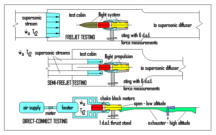
There are basically three ways to test such a device on
the ground. The first is the “freejet
test”, which is basically a
high-speed wind tunnel with heated air,
in which the entire missile is placed.
This tests for the inlet performance including vehicle attitude effects, the sized inlet/nozzle balance, and the efficiency and performance of the
combustor. What is important besides
simple supersonic airspeed is the right wind tunnel air temperature so that the
air total temperature as captured within the inlet is at the correct
value, same as it would have been in
flight at that speed. A very large
quantity of supersonic air must be sent through the wind tunnel, compared to the quantity of air that the
inlets actually capture. This is the
most expensive mode of ground testing.
The second is the “semi-freejet test”, which is also basically a high-speed wind tunnel
test, in which only the inlets are
submerged within the heated supersonic airstreams. Only the propulsion system (inlets, combustor,
and nozzle) need be tested. This
tests for the inlet performance excluding vehicle attitude effects, the sized inlet/nozzle balance, and the efficiency and performance of the
combustor. The total wind tunnel airstream quantity is
large compared to that captured by the inlets,
and it must produce the right total temperature as captured within those
inlets. But the total supersonic air
quantity is far less than that of the freejet test. This is still quite expensive, but it costs a lot less than a freejet test.
The third is the “direct-connect” (or “connected-pipe”)
test, in which a heated air supply
delivers the flight quantity of air, at
the flight total temperature, to only
the subsonic portion of the flight inlets.
This does not test for inlet capture and recovery performance or the vehicle
attitude effects upon them, and it does
not test for the sized balance of inlet and nozzle. It only tests for the efficiency and
performance of the combustor, under the
presumption that inlet performance (with vehicle attitude effects) is already
known separately. The quantity of air is
only that which would have been captured by the inlets, at the flight total temperature, and it is delivered to the inlets contained
in piping flowing subsonically, not as a
free supersonic jet. This is the most
economical way to test for combustor efficiency and performance. The relative effects of fuels, insulations,
injection schemes, and materials
of construction can also be tested most cost-effectively this way, as this is the least-expensive test
mode, by far.
---------------------------
only this far on linkedin, due to
wordcount limit
Heating the Air
There are two ways to heat the air that is delivered to the
test article in direct-connect testing:
“vitiation” and pebble-bed heaters.
In vitiation, the
airstream gets a gas fuel added to it, and combusted,
then makeup oxygen gets added back to the stream. The inert gas in this “vitiated air” stream
includes the vitiation combustion products,
not just the nitrogen and argon and trace gases that are in real
air. This requires precise real-time
computer control, to achieve the airflow
quantity and total temperature simultaneously,
and still hold the oxygen content to exactly that of air. That type of control is not cheap. For some fuels containing reactive
metals, it is not chemically
correct: the carbon dioxide and water
vaper combustion products are additional sources of oxygen, besides the basic oxygen content. That can lead to massively-erroneous test
results, especially if magnesium is involved!
The pebble bed heater is a large and massive
pre-heated bed of particles through which the airstream is percolated, to heat it up to essentially the pebble bed
preheat temperature. The result is
chemically correct air at the pre-heated bed temperature. This does not require any precise computer
control at all, and so is much, much less expensive than vitiation, and it can be used reliably with metallized
fuels.
The airflow can be fed through two lines, each with its own pebble bed heater at two
different pre-heat temperatures, and
then combined into a single mixed stream fed to the test combustor’s
inlets. In this way, by controlling the two airflows, a variable mixed temperature can be delivered
to the test article, as well as a
variable airflow rate. This only
requires the pre-programming of simple linear controls on the metering venturi
pressures, and can even be done
manually, if exacting precision is not
required in the delivered airflow and total temperature.
Pebble bed heaters are usually best done as metal balls
pre-heated electrically, but those will
have more severe max temperature limitations than vitiation. Higher temperatures closer to vitiation
capabilities are possible with combustion-gas preheat of the pebble bed, using rock or ceramic pebbles, but this risks a dusting problem that can
cause erosion of structures downstream.
These testing modes are simply not appropriate for
scramjet articles at speeds above about Mach 5 or 6, as the air heating methods are simply incapable
of supplying the necessary extreme temperatures. The usual limitations correspond with speeds
nearer Mach 3 to 4.
Altitude Simulation
There is the issue of open-air nozzle testing versus high
altitude simulation. If the ambient
atmospheric pressure is too high, it
will cause shock-separation of the flow in the supersonic portion of the
nozzle, and perhaps even unchoking of
its throat. Using a sonic-only test
nozzle profile avoids shock separation at the cost of incorrect nozzle
thrust, but cannot stop unchoke, if the backpressure is high enough. Open-air nozzle testing does allow very
informative photography.
For the freejet and semi-freejet test modes, if the test cabin is sealed, it is possible to operate the system at a
low-enough test cabin pressure so as to maintain the choke or even the full-flowing
nozzle of a test article at high-altitude conditions. The exact pressure corresponding to desired
alrtitude is not necessary, only one
such that a choked and full-flowing nozzle is maintained. Not all such facilities can do this. If the test cabin is vented to the
atmosphere, then only lower altitude
conditions may be tested that correspond to a choked, full-flowing nozzle.
Direct-connect testing is different. If the ambient backpressure precludes a
choked and full-flowing test nozzle,
then a supersonic diffuser can be installed, along with an ejector. This precludes tailpipe flame and plume
photography, but it does allow
high-altitude testing in terms of airflow rates and achieved engine
pressures. The diffuser can be sealed to
the test article with a rolling diaphragm seal.
Again, exact backpressure at the
nozzle is not required, only a pressure
such that a choked and full-flowing nozzle is maintained. The diffuser has a supersonic compression
convergence, followed by a friction
decelerator at constant area down close to Mach 1, but not actually subsonic. This is followed by a divergence in which
subsonic shockdown occurs, followed by a
significant degree of subsonic diffusion.
The subsonic stream at the diffuser outlet will likely not
be diffused all the way back up to ambient atmospheric pressure, so this is coupled to an ejector pump that
raises the pressure the rest of the way.
The working fluid for this ejector could be steam from a boiler, or it could be air from the blowdown air
supply that feeds the test article,
since test article air flows are much lower at high altitude, than they are nearer sea level.
Performance Determination
Combustor efficiency can be calculated from post-combustion
static pressures just before the nozzle entrance (termed station 4), or from measured thrust calibrated for tare
forces, or both. Note that both require a choked and
full-flowing nozzle, which is why the
backpressure unchoke is to be avoided at all costs. There is no such thing as a tare
pressure, so if the sources of data disagree
on the efficiency, trust the data
derived from static pressure; you simply
do not have your facility tare forces properly calibrated.
For pressure-based performance, your nozzle entrance contraction ratio and
expected combustion gas specific heat ratio provide the ratio of chamber
combusted stagnation pressure Pt4 to the measured combusted static
pressure P4. You need to know
very precisely the flowrates of air wa and fuel wf and
any ablated liner massflow wabl.
Their sum is the total massflow at station 4 w4. You will also need the value of the discharge
coefficient CD at the ramjet throat (station 5), something determined separately by flow
calibration testing. But for good nozzle
designs, it is never very far from 0.98.
The choked massflow equation determines combusted
characteristic velocity c*4 = Pt4 CD A5
gc/w4, where gc
is the gravity constant that makes the units consistent. The fuel to air ratio, the inlet total temperature Tt2, and theoretical thermochemical calculations
done at the measured P4 will produce a theoretical combusted
characteristic velocity c*o4. Their ratio is the stream thrust combustion
efficiency ηcSA
= c*4/c*o4.
For thrust-based performance, you will need the same estimates of Pt4, A5, and specific heat ratio as were used in the
pressure-based analysis, the
tare-corrected thrust measurement also corrected for any supersonic diffuser
forces (thus being the actual nozzle thrust Fnoz), the exit area A6, the half-angle of that exit cone a, and the ambient or altitude diffuser pressure
around the nozzle exit P7.
The nozzle kinetic energy efficiency calculates as ηKE
= 0.5*(1 + cos(a)), where a is simple if
a conical nozzle, or the average of
near-throat and exit-lip values, if a
curved bell.
The nozzle exit ratio A6/A5, kinetic energy efficiency, and combustion
gas specific heat ratio allow you to compute the vacuum thrust coefficient CFvac
by standard ballistic methods. That plus
the values of A6 and P7 allow you to compute the actual
thrust coefficient CF. Then
the thrust-effective Pt4 = Fnoz/CF A5. From there,
the analysis is exactly the same as pressure-based, all the way to ηcSA.
To meet combustion efficiency definition reporting requirements per the Chemical Propulsion Information Agency (CPIA) standards, you must convert these stream thrust efficiencies (both bases) to the temperature-rise basis that is considered standard for ramjet work, where Tot4 is the theoretical combusted total temperature from your thermochemical calculation:
ηcΔT
= (Tot4*ηcSA2 – Tt2)/(Tot4
– Tt2).
Final Comments
I’ve tried to describe the bare
bones of testing ramjets on the ground.
There’s a whole lot of nitty-gritty details I left out. Describing all of that is closer to a book
than just an article.

No comments:
Post a Comment